
User's Guide
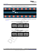
Table Of Contents
- CC3235MODSF SimpleLink™ Wi-Fi® and IoT Solution With MCU LaunchPad™ Hardware
- Table of Contents
- 1 Introduction
- 2 Hardware
- 2.1 Block Diagram
- 2.2 Hardware Features
- 2.2.1 Key Benefits
- 2.2.2 XDS110-Based Onboard Debug Probe
- 2.2.3 Debug Probe Connection: Isolation Jumper Block
- 2.2.4 Application (or "Backchannel") UART
- 2.2.5 JTAG Headers
- 2.2.6 Using the XDS110 Debug Probe with a Different Target
- 2.2.7 Power Connections
- 2.2.8 Reset Pullup Jumper
- 2.2.9 Clocking
- 2.2.10 I2C Connection
- 2.2.11 Sense on Power (SOP)
- 2.2.12 Push-Buttons and LED Indicators
- 2.3 Electrical Characteristics
- 2.4 Antenna Characteristics
- 2.5 BoosterPack™ Plug-in Module Pinout
- 3 Layout Guidelines
- 4 Operational Setup and Testing
- 5 Development Environment Requirements
- 6 Additional Resources
- 7 Assembly Drawing and Schematics
- Appendix A Manual Information to the End User
- Revision History
- Important Notice

TI Confidential – NDA Restrictions
Operational Setup and Testing
www.ti.com
38
SWRU548A–February 2019–Revised August 2019
Submit Documentation Feedback
Copyright © 2019, Texas Instruments Incorporated
CC3235MODSF LaunchPad™ Development Kit (LAUNCHCC3235MOD)
4.1 Measuring the CC3235MOD Current Draw
To measure the current draw of the CC3235MOD device using a multimeter, use the VBAT jumper on the
J101 isolation block. The current draw measured in this mode includes only the CC3235MOD device, the
Serial Flash internal to the module, and any current drawn through the BoosterPack plug-in module
headers. Furthermore, if the module's GPIO is driving a high current load such as an LED, then this will
also be included in the measurement.
4.1.1 Low-Current Measurement with USB Power ( <1 mA)
See the following instructions to measure ultra-low power when powering with a USB cable.
1. Remove the VBAT jumper in the J101 isolation block, and attach an ammeter across this jumper. See
Figure 26.
2. Consider the effect that the backchannel UART and any circuitry attached to the CC3235MOD may
have on current draw. Consider disconnecting these at the siolation jumper block, or at least consider
their current sinking and sourcing capability in the final measurement.
3. Begin target execution and set the device to low-power modes (LPDS or hibernate).
4. Measure the current. Remember that if the current levels are fluctuating, it may be difficult to get a
stable measurement. It is easier to measure quiescent states. See the "Power Measurement Guide" in
CC3135, CC3235x SimpleLink™ Wi-Fi® Internet-on-a chip™ Networking Subsystem Power
Management for more current consumption measurement techniques.
Figure 26. Low Current Measurement