
User's Guide

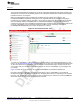
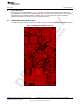

Table Of Contents
- CC3235MODSF SimpleLink™ Wi-Fi® and IoT Solution With MCU LaunchPad™ Hardware
- Table of Contents
- 1 Introduction
- 2 Hardware
- 2.1 Block Diagram
- 2.2 Hardware Features
- 2.2.1 Key Benefits
- 2.2.2 XDS110-Based Onboard Debug Probe
- 2.2.3 Debug Probe Connection: Isolation Jumper Block
- 2.2.4 Application (or "Backchannel") UART
- 2.2.5 JTAG Headers
- 2.2.6 Using the XDS110 Debug Probe with a Different Target
- 2.2.7 Power Connections
- 2.2.8 Reset Pullup Jumper
- 2.2.9 Clocking
- 2.2.10 I2C Connection
- 2.2.11 Sense on Power (SOP)
- 2.2.12 Push-Buttons and LED Indicators
- 2.3 Electrical Characteristics
- 2.4 Antenna Characteristics
- 2.5 BoosterPack™ Plug-in Module Pinout
- 3 Layout Guidelines
- 4 Operational Setup and Testing
- 5 Development Environment Requirements
- 6 Additional Resources
- 7 Assembly Drawing and Schematics
- Appendix A Manual Information to the End User
- Revision History
- Important Notice

TI Confidential – NDA Restrictions
www.ti.com
Hardware
27
SWRU548A–February 2019–Revised August 2019
Submit Documentation Feedback
Copyright © 2019, Texas Instruments Incorporated
CC3235MODSF LaunchPad™ Development Kit (LAUNCHCC3235MOD)
2.5 BoosterPack™ Plug-in Module Pinout
The LaunchPad development kit adheres to the 40-pin LaunchPad development kit pinout standard. This
standard was created to aid compatibility between LaunchPad development kits and BoosterPack plug-in
modules across the TI ecosystem.
While most BoosterPack plug-in modules are compliant with the standard, some are not. The
LAUNCHCC3235MOD LaunchPad development kit is compatible with all 40-pin BoosterPack plug-in
modules that are compliant with the standard. If the reseller or owner of the BoosterPack plug-in module
does not explicitly indicate compatibility with the LAUNCHCC3235MOD LaunchPad development kit,
compare the schematic of the candidate BoosterPack plug-in module with the LaunchPad development kit
to ensure compatibility. Keep in mind that sometimes conflicts can be resolved by changing the
CC3235MODSF12MOB device pin function configuration in software.
Figure 15. BoosterPack Checker Tool
To check the compatibility of a BoosterPack plug-in module with the LaunchPad development kit of your
choice, use the BoosterPack Checker Tool. This allows you to select any LaunchPad development kit that
TI offers and determine its compatibility with any number of BoosterPack plug-in modules that we offer.
You can also add your own BoosterPack plug-in module to check its compatibility as you prototype that
next design.
Figure 16 shows the 40-pin pinout of the LAUNCHCC3235MOD LaunchPad development kit.
Note that software's configuration of the pin functions plays a role in compatibility. The LaunchPad
development kit side of the dashed line shows only the applicable function for conforming to the standard.
However, each pin has other functionality that can be configured by the software. See the CC3235MODx
device data sheet for more details on individual pin functions.