
User's Guide
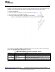
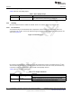
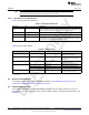
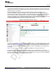
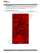

Table Of Contents
- CC3235MODSF SimpleLink™ Wi-Fi® and IoT Solution With MCU LaunchPad™ Hardware
- Table of Contents
- 1 Introduction
- 2 Hardware
- 2.1 Block Diagram
- 2.2 Hardware Features
- 2.2.1 Key Benefits
- 2.2.2 XDS110-Based Onboard Debug Probe
- 2.2.3 Debug Probe Connection: Isolation Jumper Block
- 2.2.4 Application (or "Backchannel") UART
- 2.2.5 JTAG Headers
- 2.2.6 Using the XDS110 Debug Probe with a Different Target
- 2.2.7 Power Connections
- 2.2.8 Reset Pullup Jumper
- 2.2.9 Clocking
- 2.2.10 I2C Connection
- 2.2.11 Sense on Power (SOP)
- 2.2.12 Push-Buttons and LED Indicators
- 2.3 Electrical Characteristics
- 2.4 Antenna Characteristics
- 2.5 BoosterPack™ Plug-in Module Pinout
- 3 Layout Guidelines
- 4 Operational Setup and Testing
- 5 Development Environment Requirements
- 6 Additional Resources
- 7 Assembly Drawing and Schematics
- Appendix A Manual Information to the End User
- Revision History
- Important Notice

TI Confidential – NDA Restrictions
Hardware
www.ti.com
24
SWRU548A–February 2019–Revised August 2019
Submit Documentation Feedback
Copyright © 2019, Texas Instruments Incorporated
CC3235MODSF LaunchPad™ Development Kit (LAUNCHCC3235MOD)
2.2.8 Reset Pullup Jumper
Table 3 lists the reset pullup jumper.
Table 3. Reset Pullup Jumper
Reference Use Comments
J13 RESET pullup Install this jumper to enable the pullup resistor on the nRESET pin of the
device, when the board is powered from an external supply.
2.2.9 Clocking
All of the required clocks are inside the module. There is no need to supply any external clock.
2.2.10 I
2
C Connection
The board features an accelerometer and a temperature sensor for the out-of-box demo. These are
connected to the I
2
C bus, and can be isolated using the jumpers provided (shown as yellow jumpers J23
and J24 in Figure 13).
Figure 13. I
2
C Connections
By removing J23 and J24, the accelerometer and the temperature sensors are isolated from the I
2
C bus.
This measure also removes the I
2
C pullup resistors from the sensor side of the circuit, and therefore any
connection to the circuit requires the user to install external pullup resistors.
Table 4 lists the I
2
C jumper definitions.
Table 4. I
2
C Jumper Definitions
Reference Use Comments
J23 I2C SCL Populated: CC3235MOD SCL connected to onboard sensors with pullup
Open: CC3235MOD SCL disconnected from onboard sensors
J24 I2C SDA Populated: CC3235MOD SDA connected to onboard sensors with pullup
Open: CC3235MOD SDA disconnected from onboard sensors