s CC3235MODSF SimpleLink™ Wi-Fi® and IoT Solution With MCU LaunchPad™ Hardware ide nt ia l– ND A Re str ict ion User's Guide TI Co nf Literature Number: SWRU548A February 2019 – Revised August 2019
Contents 1 Introduction ......................................................................................................................... 6 ........................................................................................ 6 1.2 LAUNCHCC3235MOD Key Features ................................................................................. 7 1.3 What's Included .......................................................................................................... 7 1.4 REACH Compliance ....
www.ti.com A.4 EU Certification and Statement...................................................................................... 52 A.5 CC3235MODx Approved Antennas ................................................................................. 53 TI Co nf ide nt ia l– ND A Re str ict ion s Revision History ..........................................................................................................................
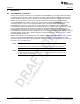
User's Guide SWRU548A – February 2019 – Revised August 2019 CC3235MODSF LaunchPad™ Development Kit (LAUNCHCC3235MOD) str ict ion s Start your design with the industry's first programmable FCC, IC/ISED, ETSI/CE, and MIC Certified SimpleLinkTM Wi-Fi® CC3235MOD Dual-Band Wireless Microcontroller Module with built-in Dual-Band (2.4 GHz and 5 GHz) Wi-Fi® connectivity.
www.ti.com TI Co nf ide nt ia l– ND A Re str ict ion s Figure 1.
Introduction www.ti.com 1 Introduction 1.1 CC3235MODSF LaunchPad™ Created for the Internet of Things (IoT), the SimpleLink CC3235MODx is a wireless module with built-in Dual-Band Wi-Fi connectivity for the LaunchPad ecosystem, which integrates a high-performance Arm® Cortex®-M4 MCU and lets customers develop an entire application with one device. With on-chip Wi-Fi, Internet, and robust security protocols, no prior Wi-Fi experience is required for fast development.
Introduction www.ti.com 1.2 LAUNCHCC3235MOD Key Features ND A Re str ict ion s The LAUNCHCC3235MOD SimpleLink LaunchPad includes the following features: • CC3235MODSF, SimpleLinkTM Dual-Band Wi-Fi® module solution – Integrated MCU – 40.0-MHz Crystal – 32.
Introduction 1.5 www.ti.com Regulatory Compliance The SimpleLinkTM CC3235MODx Wi-FI® LaunchPadsTM are tested for and found to be in compliance with FCC and ISED regulations regarding unlicensed intentional radiators. Hereby, Texas Instruments Inc. declares that the radio equipment type LAUNCHCC3235MOD are in compliance with Directive 2014/53/EU.
Introduction www.ti.com 1.7 Next Steps: Looking into the Provided Code After the EVM features have been explored, the user can open an integrated development environment and start editing the code examples from the SDK. See Section 6.2 for available IDEs and where to download them. The Out-of-Box source code and more code examples are provided in the CC3235 SDK. Code is licensed under BSD, and TI encourages reuse and modifications to fit specific needs.
Hardware 2 www.ti.com Hardware Figure 2 shows the CC3235MODSF LaunchPad EVM. TI Co nf ide nt ia l– ND A Re str ict ion s Figure 2.
Hardware www.ti.com 2.1 Block Diagram Figure 3 shows a functional block diagram of the CC3235MODx module. Figure 3. CC3235MODx Functional Block Diagram CC3235 40 MHz RF_ABG 32.768 kHz F nReset Aband 5 GHz SPDT D F str WRF_A 2.3 V to 3.
Hardware www.ti.com Figure 4 shows a functional block diagram of the LAUNCHCC3235MOD SimpleLink LaunchPad. Figure 4. LAUNCHCC3235MOD Functional Block Diagram Acc BMA280 FTDI FT2232D and SWD Circuit JTAG and SWD INT (GPIO13) UART (Flashing) I 2C Temperature Sensor TMP116 ion s USB Connector CC3235MODSF12MOBR VCC str Reverse Protection Re Two AA Battery Connectors ict LDO 3.
Hardware www.ti.com Hardware Features • • • 2.2.1 s ion • • CC3235MODSF, SimpleLinkTM Dual-Band Wi-Fi® module solution with integrated MCU 40-pin LaunchPad™ standard that leverages the BoosterPack™ ecosystem TI Standard XDS110-based JTAG emulation with serial port for flash programming Supports both 4-wire JTAG and 2-wire SWD Two buttons and a RGB LED for user interaction Virtual COM port UART through USB on PC Onboard chip antenna with U.
Hardware s Wi-Fi network processor subsystem: – Wi-Fi® core: • 802.11 a/b/g/n 2.4 GHz and 5 GHz • Modes: • Access Point (AP) • Station (STA) • Wi-Fi Direct® (only supported on 2.4 GHz) • Security: • WEP • WPA™/WPA2™ PSK • WPA2 Enterprise – Internet and application protocols: • HTTPs server, mDNS, DNS-SD, DHCP • IPv4 and IPv6 TCP/IP stack • 16 BSD sockets (fully secured TLS v1.2 and SSL 3.
Hardware ion TI Co nf ide nt ia l– • ND A • Re str • Power-Management Subsystem: – Integrated DC/DC converters support a wide range of supply voltage: • Single wide-voltage supply, VBAT: 2.3 V to 3.6 V – Advanced low-power modes: • Shutdown: 1 µA, hibernate: 5.5 µA • Low-power deep sleep (LPDS): 120 µA • Idle connected (MCU in LPDS): 710 µA • RX traffic (MCU active): 59 mA • TX traffic (MCU active): 223 mA – Wi-Fi TX Power • 2.4 GHz: 16 dBm at 1 DSSS • 5 GHz: 15.
Hardware 2.2.2 www.ti.com XDS110-Based Onboard Debug Probe To keep development easy and cost effective, TI's LaunchPad development kits integrate an onboard debug probe, which eliminates the need for expensive programmers. The CC3235MODSF LaunchPad has the XDS-110-based debug probe (see Figure 5), which is a simple and low-cost debugger that supports nearly all TI Arm device derivatives. l– ND A Re str ict ion s Figure 5.
Hardware www.ti.com 2.2.3 Debug Probe Connection: Isolation Jumper Block The isolation jumper block at jumper J101 allows the user to connect or disconnect signals that cross from the XDS110 domain into the CC3235MOD target domain. This includes JTAG signals, application UART signals, and 3.3-V and 5-V power.
Hardware 2.2.4 www.ti.com Application (or "Backchannel") UART The board supports a USB-based virtual COM port, using the SimpeLink™ MSP432E401Y Arm® MCU. The LaunchPad is shipped with the UART lines from the CC3235MODSF connected to the UART on the MSP432E4 MCU. The CC3235MODSF's UART can also be routed to the 20-pin connector for use as a GPIO or external UART. The selection is performed using jumpers on the board. Figure 6 shows the UART routed to USB COM port.
Hardware www.ti.com 2.2.5 JTAG Headers The headers are provided on the board to isolate the CC3235MOD from the onboard XDS110-based JTAG emulator. These jumpers are shorted by default when the board is shipped from TI. Figure 5 and Table 1 are for default configurations, and Figure 8 shows the external emulator connection. To connect an external emulator, remove the isolation block JTAG jumpers and place the external emulator on the JTAG IN connector.
Hardware 2.2.6 www.ti.com Using the XDS110 Debug Probe with a Different Target The XDS110 debug probe on the LaunchPad development kit can interface to most Arm® Cortex®-M devices, not just the onboard target CC3235MODSF device. This functionality is enabled by the J2 10-pin Cortex-M JTAG connector (see Figure 9) and a 10-pin cable, such as the FFSD-05-D-06.00-01-N (sold separately from the LaunchPad development kit). l– ND A Re str ict ion s Figure 9.
Hardware www.ti.com 2.2.7 Power Connections The board accommodates various power methods, including through the onboard XDS110 as well as external or BoosterPack plug-in module power (see Figure 10). TI Co nf ide nt ia l– ND A Re str ict ion s Figure 10.
Hardware 2.2.7.1 www.ti.com XDS110 USB Power The most common power-supply scenario is from USB through the XDS110 debugger. This provides 5-V power from the USB and also regulates this power rail to 3.3 V for XDS110 operation and 3.3-V to the target side of the LaunchPad development kit. Power from the XDS110 is controlled by jumper J101. When the board is powered from the USB connector, ensure that the jumpers are placed on the following headers, shown in Figure 11.
Hardware www.ti.com 2.2.7.2 BoosterPack Plug-in Module and External Power Supply Headers J19 and J20 are present on the board to supply external power directly when USB power is not available. Use the following precautions before using the board with an external power supply. 1. 2. 3. 4. Remove the USB cable. Ensure that jumpers are only placed on the headers shown in Figure 12. Use a jumper wire to connect VBAT and BRD. Plug in the external power supply on J20 with the correct polarity.
Hardware 2.2.8 www.ti.com Reset Pullup Jumper Table 3 lists the reset pullup jumper. Table 3. Reset Pullup Jumper 2.2.9 Reference Use Comments J13 RESET pullup Install this jumper to enable the pullup resistor on the nRESET pin of the device, when the board is powered from an external supply. Clocking I2C Connection ion 2.2.10 s All of the required clocks are inside the module. There is no need to supply any external clock.
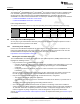
Hardware www.ti.com 2.2.10.1 Default I2C Addresses Table 5 lists the default I2C addresses of the onboard sensors. Table 5. Default I2C Addresses (of Onboard Sensors) 2.2.
Hardware www.ti.com NOTE: Placing no jumpers on the block ensures that the line is pulled low using 100K pull down resistors. Placing the jumper pulls the pin high using a 10K resistor. 2.2.12 Push-Buttons and LED Indicators Table 7 lists the push-button definitions. Table 7. Push-Button Definitions Use Comments SW1 RESET This is used to reset the CC3235MOD device. This signal is also output on the 20-pin connector to reset any external BoosterPack which may be stacked.
Hardware www.ti.com 2.5 BoosterPack™ Plug-in Module Pinout The LaunchPad development kit adheres to the 40-pin LaunchPad development kit pinout standard. This standard was created to aid compatibility between LaunchPad development kits and BoosterPack plug-in modules across the TI ecosystem. While most BoosterPack plug-in modules are compliant with the standard, some are not.
Hardware www.ti.com Re str ict ion s Figure 16. LAUNCHCC3235MOD BoosterPack™ Header Pin Assignments A NOTE: RESET output is an open-drain-type output and can only drive the pin low. The pullup ensures that the line is pulled back high when the button is released. No external BoosterPack can drive this pin low. TI Co nf ide nt ia l– ND All the signals are referred to by the pin number in the SDK; Figure 16 shows the default mappings. Some of the pins are repeated across the connector.
Layout Guidelines www.ti.com 3 Layout Guidelines The integrator of the CC3235MODx !~and CC3235MODAx modules must comply with the PCB layout recommendations described in the following subsections to preserve and minimize the risk with regulatory certifications for FCC, ISED/IC, ETSI/CE, and MIC. Also, TI recommends that customers follow the guidelines described in this section to achieve similar performance. 3.1 LAUNCHCC3235MOD Board Layout The reference layout consists of a four-layer design.
Layout Guidelines www.ti.com Figure 18 shows the LAUNCHCC3235MOD first inner layer. TI Co nf ide nt ia l– ND A Re str ict ion s Figure 18.
Layout Guidelines www.ti.com Figure 19 shows the LAUNCHCC3235MOD second inner layer. TI Co nf ide nt ia l– ND A Re str ict ion s Figure 19.
Layout Guidelines www.ti.com Figure 20 shows the LAUNCHCC3235MOD bottom layer. TI Co nf ide nt ia l– ND A Re str ict ion s Figure 20.
Layout Guidelines www.ti.com 3.2 General Layout Recommendations Ensure that the following general layout recommendations are followed: • Have a solid ground plane and ground vias under the module for stable system and thermal dissipation. • Do not run signal traces underneath the module on a layer where the module is mounted. 3.3 RF Layout Recommendations The RF section of this wireless module gets top priority in terms of layout.
Layout Guidelines www.ti.com Use the following RF layout recommendations for the CC3235MODx module: • RF traces must have 50-Ω impedance. • RF trace bends must be made with gradual curves, and 90 degree bends must be avoided. • RF traces must not have sharp corners. • There must be no traces or ground under the antenna section. • RF traces must have via stitching on the ground plane beside the RF trace on both sides. • RF traces must be as short as possible.
Layout Guidelines www.ti.com 3.4 Antenna Placement and Routing The antenna is the element used to convert the guided waves on the PCB traces to the free space electromagnetic radiation. The placement and layout of the antenna are the keys to increased range and data rates. Table 9 provides a summary of the recommended antennas to use with the CC3235MODx module. Table 9. Antenna Guidelines SR NO. GUIDELINES Place the antenna on an edge or corner of the PCB.
Layout Guidelines www.ti.com Figure 24 shows the top view of the coplanar waveguide with GND and via stitching. Figure 24. CPW With GND and Via Stitching (Top View) S ict ion s W str The recommended values for the PCB are provided for 2-layer boards in Table 10 and for 4-layer boards in Table 11. PARAMETER Re Table 10. Recommended PCB Values for 2-Layer Board (L1 to L2 = 42.1 mils) VALUE UNIT mils 5.5 42.1 Er (FR-4 substrate) 4.2 mils mils F/m l– S H A 26 ND W nt ia Table 11.
Operational Setup and Testing www.ti.com 4 Operational Setup and Testing A compatible BoosterPack can be stacked on top of the LaunchPad using the two, 20-pin connectors. The connectors do not have a key to prevent the misalignment of the pins or reverse connection. Ensure that the VCC and 5-V pins are aligned with the BoosterPack header pins. On the CC3235MODSF LaunchPad, a small white symbol is provided near pin 1 (see Figure 25) to orient all BoosterPacks.
Operational Setup and Testing 4.1 www.ti.com Measuring the CC3235MOD Current Draw To measure the current draw of the CC3235MOD device using a multimeter, use the VBAT jumper on the J101 isolation block. The current draw measured in this mode includes only the CC3235MOD device, the Serial Flash internal to the module, and any current drawn through the BoosterPack plug-in module headers.
Operational Setup and Testing www.ti.com 4.1.2 Active Current Measurements s See the following instructions to measure active power. 1. Remove the VBAT jumper (J18) as shown in Figure 27. 2. Solder a 0.1-Ω resistor on a wire which can be connected to a voltmeter/oscilloscope. Or, attach a jumper across J18 so that it can be used with a current probe. 3. Measure the voltage across the resistor using an oscilloscope with a differential probe.
Operational Setup and Testing 4.2 4.2.1 www.ti.com RF Connections AP Connection Testing By default, the board ships with the 2.4 GHz and 5 GHz RF signals routed to the onboard chip antenna, as shown in Figure 28. A Re str ict ion s Figure 28. Using Onboard Antenna (Default Condition) ND A U.FL connector J17 provides a way to test in the lab using a compatible cable. Alternatively, trackpads for an SMA connector J15 are provided onboard to replace the J17 U.
Operational Setup and Testing www.ti.com 4.3 4.3.1 Design Files Hardware Design Files Schematics can be found in Section 7.2. All design files, including schematics, layout, Bill of Materials (BOM), Gerber files, and documentation are available for download from LAUNCHCC3235MOD. 4.4 Software Development Environment Requirements ion 5 s All design files, including firmware patches, software example projects, and documentation are available from the CC3235 Software Development Kit.
Additional Resources www.ti.com 6 Additional Resources 6.1 CC3235MODx Product Page For more information on the CC3235MODSF device, visit the CC3235MODSF product page, which includes the CC3235MODx SimpleLink™ Wi-Fi® Wireless and Internet-of-Things Solution, a Single-Chip Wireless MCU data sheet and key documents such as the CC32xx SimpleLink™ Wi-Fi® and Internet-ofThings Technical Reference Manual. For more information on the CC3235MODS device, visit the CC3235MODS product page. 6.
Assembly Drawing and Schematics www.ti.com 7 Assembly Drawing and Schematics 7.1 Assembly Drawing TI Co nf ide nt ia l– ND A Re str ict ion s Figure 31.
Assembly Drawing and Schematics 7.2 www.ti.com Schematics Figure 32. Schematics (1 of 5) U1A s MSP432E4 HOST MCU FOR EMULATION U1B 95 96 91 C1 92 0.1uF 121 120 PB0 PB1 PB2 PB3 PB4 PB5 GND ITCK ITMS ITDI ITDO 100 99 98 97 25 24 23 22 VBUS_USB1 R11 330k 1 2 3 LED1 4 125 126 127 128 LED0 R12 220k C2 0.
Assembly Drawing and Schematics www.ti.com Figure 33.
Assembly Drawing and Schematics www.ti.com Figure 34.
Assembly Drawing and Schematics www.ti.com Figure 35.
Assembly Drawing and Schematics www.ti.com Figure 36. Schematics (5 of 5) BOOSTER PACK INTERFACE For Antenna diversity P1 ANA_IN3 +3.
Appendix A SWRU548A – February 2019 – Revised August 2019 Manual Information to the End User A.1 End User Manual RF Function and Frequency Range ict A.2 ion s The OEM integrator must be aware not to provide information to the end user regarding how to install or remove this RF module in the user’s manual of the end product which integrates this module. The end user manual must include all required regulatory information and warnings as shown in this manual.
FCC and IC Certification and Statement www.ti.com You are cautioned that changes or modifications not expressly approved by the party responsible for compliance could void the user’s authority to operate the equipment. This device complies with Part 15 of the FCC Rules. Operation is subject to the following two conditions: • • This device may not cause harmful interference. This device must accept any interference received, including interference that may cause undesired operation of the device.
FCC and IC Certification and Statement www.ti.com CAUTION IC RF Radiation Exposure Statement: This equipment complies with IC radiation exposure limits set forth for an uncontrolled environment. This equipment should be installed and operated with a minimum distance of 20 cm between the radiator and your body. Déclaration d'exposition aux radiations: ion s Cut équipement est conforme aux limites d'exposition aux rayonnements IC établies pour un environnement non contrôlé.
FCC and IC Certification and Statement A.3.5 www.ti.com FCC Definitions Portable: (§2.1093)— A portable device is defined as a transmitting device designed to be used so that the radiating structures of the device is or are within 20 centimeters of the body of the user. A.3.6 ion s Mobile: (§2.
EU Certification and Statement www.ti.com A.4.2.2 LAUNCHCC3235MOD Hereby, Texas Instruments declares that the radio equipment type LAUNCHCC3235MOD is in compliance with Directive 2014/53/EU. The full text of the EU declaration of conformity are available at LAUNCHCC3235MOD EC Declaration of Conformity (DoC). A.4.3 Waste Electrical and Electronic Equipment (WEEE) OEM and Host Manufacturer Responsibilities ict A.4.
Revision History www.ti.com Revision History NOTE: Page numbers for previous revisions may differ from page numbers in the current version. Changes from Original (February 2019) to A Revision .................................................................................................. Page Re str ict ion s Updated CC3235MODSF SimpleLink™ Wi-Fi® LaunchPad™ Development Kit image. ........................................ 5 Added note to CC3220 LaunchPad™ section ...................................
IMPORTANT NOTICE AND DISCLAIMER TI PROVIDES TECHNICAL AND RELIABILITY DATA (INCLUDING DATASHEETS), DESIGN RESOURCES (INCLUDING REFERENCE DESIGNS), APPLICATION OR OTHER DESIGN ADVICE, WEB TOOLS, SAFETY INFORMATION, AND OTHER RESOURCES “AS IS” AND WITH ALL FAULTS, AND DISCLAIMS ALL WARRANTIES, EXPRESS AND IMPLIED, INCLUDING WITHOUT LIMITATION ANY IMPLIED WARRANTIES OF MERCHANTABILITY, FITNESS FOR A PARTICULAR PURPOSE OR NON-INFRINGEMENT OF THIRD PARTY INTELLECTUAL PROPERTY RIGHTS.