
User manual
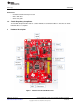

UART for Flashing Mode
UART for BoosterPack
www.ti.com
Hardware Description
Table 3. Default I2C Addresses
Sensor Type Ref Part Number Slave Address
Temp sensor U6 TMP008 0x41
Accelerometer U10 BMA222 0x18
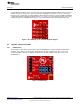
2.4.3 Power Connections
The board can be powered by using the on-board micro USB connector. An on-board LDO provides 3.3 V
for the CC3200 and the rest of the board to operate. This supply can be isolated from the LDO using the
jumpers on the board.
Table 4. Jumper Settings
Reference Usage Comments
J12 Current Measures the current flowing into the CC3200 device.
measurement
J13 Board power Short: Supply the board power from the on-board LDO.
Open: Supply the board power from the J20 (battery connector)
J19 5 V power 5 V output from the USB VBUS (has a diode drop of up to 0.4 V)
J20 3.3 V power input Can be used to power the board from an external 2XAA battery pack. It has in-built reverse
voltage protection to prevent the battery from being plugged in the reverse manner.
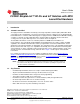
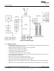
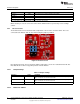
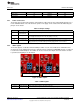
2.4.4 UART Signals
The board supports a USB-based virtual COM port, which is used on the FTDI device FT2232D. There
are two ports on the FT2232: the first port is dedicated for the emulation (JTAG/SWD) and the second port
is used for the virtual COM port. The UART can also be routed to the 20-pin connector and the selection
is performed using jumpers on the board.
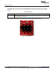
Figure 6. UART Signals
Table 5. UART Signals
Reference Usage Comments
J6, J7 UART for Flash Short 1-2: Route the signals to the 20 pin connector.
programming Short 2-3: Route the signals to the FTDI for Flash programming.
9
SWRU372–June 2014 CC3200 SimpleLink™ Wi-Fi
®
and IoT Solution with MCU LaunchPad
Hardware
Submit Documentation Feedback
Copyright © 2014, Texas Instruments Incorporated