CC3200 SimpleLink™ Wi-Fi® and IoT Solution with MCU LaunchPad Hardware User's Guide Literature Number: SWRU372 June 2014
Contents 1 Introduction ......................................................................................................................... 4 1.1 2 3 4 5 2 CC3200 LaunchPad ..................................................................................................... 4 ............................................................................................................. 4 ..........................................................................................................
www.ti.com List of Figures 1 CC3200 LaunchPad EVM Overview ...................................................................................... 5 2 CC3200 Block Diagram ..................................................................................................... 6 3 Pn-1 Marking on the LaunchPad (white triangle) ........................................................................ 7 4 JTAG Headers 5 I2C Connections ......................................................................
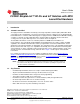
User's Guide SWRU372 – June 2014 CC3200 SimpleLink™ Wi-Fi® and IoT Solution with MCU LaunchPad Hardware 1 Introduction 1.1 CC3200 LaunchPad The high performance CC3200 is the industry's first single-chip Microcontroller (MCU) with built-in Wi-Fi connectivity for the LaunchPad™ ecosystem. Created for the Internet of Things (IoT), the SimpleLink WiFi CC3200 device is a wireless MCU that integrates a high-performance ARM® Cortex®-M4 MCU allowing customers to develop an entire application with a single IC.
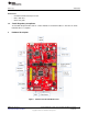
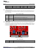
Introduction www.ti.com 1.3 What's Included Kit Contents • CC3200 LaunchPad development tool • Micro USB cable • Quick start guide 1.4 FCC/IC Regulatory Compliance The CC3200 SimpleLink Wi-Fi and IoT solution with MCU LaunchPad hardware is FCC Part 15 and IC ICES-003 Class A compliant. 2 Hardware Description Figure 1.
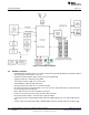
Hardware Description 2.1 www.ti.com Block Diagram Figure 2. CC3200 Block Diagram 2.2 Hardware Features • • • • • • • • • • • • 6 CC3200, SimpleLink Wi-Fi, internet-on-a-chip solution with integrated MCU40-pin LaunchPad standard that leverages the BoosterPack ecosystem FTDI-based JTAG emulation with serial port for Flash programming Supports both 4-wire JTAG and 2-wire SWD Two buttons and three LEDs for user interaction Virtual COM port UART through USB on PC On-board chip antenna with U.
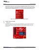
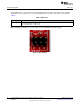
Hardware Description www.ti.com 2.3 Connecting a BoosterPack A compatible BoosterPack can be stacked on top of the LaunchPad using the 2x20 pin connectors. Note that the connectors do not have a “key” to prevent the misalignment of the pins or reverse connection. Ensure that Vcc and 5V pins, are aligned with the BoosterPack header pins. On the CC3200 LaunchPad, a small white triangle symbol is provided near Pin-1 (see Figure 3) to orient all BoosterPacks.
Hardware Description www.ti.com Table 1. JTAG Headers Reference J8 (TCK) (1) J9 (TMS) (1) Usage Comments JTAG Short : Routes the on-board emulator to the CC3200 J10 (TDI) Open: Isolate the on-board emulator from the CC3200. J11(TDO) (1) For the SWD mode, only TCK and TMS need to be shorted to the CC3200. When a battery is used, be sure to disconnect all the JTAG headers to prevent any reverse leakage current. 2.4.
Hardware Description www.ti.com Table 3. Default I2C Addresses 2.4.3 Sensor Type Ref Part Number Slave Address Temp sensor U6 TMP008 0x41 Accelerometer U10 BMA222 0x18 Power Connections The board can be powered by using the on-board micro USB connector. An on-board LDO provides 3.3 V for the CC3200 and the rest of the board to operate. This supply can be isolated from the LDO using the jumpers on the board. Table 4. Jumper Settings 2.4.
Hardware Description 2.4.5 www.ti.com Sense on Power The CC3200 can be set to operate in three different modes based on the state of the Sense on Power (SOP) lines. These are pins 21, 34, 35 on the CC3200 device. The state of the device is described in Table 6. Table 6. SOP Lines Usage SOP[2:0] Comments 100 = Flash programming 000 = Functional mode + 4 Wire JTAG 001 = Functional mode + 2 Wire JTAG Note: SOP[2:0] corresponds to J15, J16, and J17, in the LaunchPad schematic design. Figure 7.
Hardware Description www.ti.com 2.4.6 Other Miscellaneous Table 7. Miscellaneous Settings Reference Usage J4 Accelerometer Interrupt Short = Route the Accelerometer sensor interrupt to the GPIO_13 Open = Isolates the Interrupt to the GPIO_13 J5 Debug Header To observe the Network Processor (NWP), MAC Logs.
Hardware Description 2.4.7 www.ti.com Push Buttons and LEDs Table 8. Push Buttons Reference Usage Comments SW1 RESET This is used to RESET the CC3200 device. This signal is also output on the 20-pin connector to RESET any external BoosterPack which may be stacked. SW2 GPIO_22 When pushed, the GPIO_22 will be pulled to VCC. SW3 GPIO_13 When pushed, the GPIO_13 will be pulled to VCC.
Hardware Description www.ti.com Table 9. LEDs Refere nce Colo4 Usage D1 Yellow nRESET This LED is used to indicate the state of nRESET pin. If this LED is glowing, the device is functional. D2 Green Debug This LED glows whenever the debugging it enabled over the JTAG D4 RED Power Indicates when the 3.3 V power is supplied to the board.
Hardware Description 2.4.8 www.ti.com 2x20 Pin Connector Assignment The signal assignment on the 2x20 pin connector is shown in Figure 8. The P1-Pn naming convention is used for 2x20 pin connectors only. P1 P3 Dev Dev Ref Signal Pin# Pin# Signal 1 3.
Hardware Description www.ti.com 2.5.1 USB Power The LaunchPad is designed to work from the USB provided power supply. The LaunchPad will enumerate as a bus-powered device on the computer. When the board is powered from the USB connector, make sure that the jumpers are placed on the following headers, as shown in Figure 9. J12 (shorted) J13 (shorted) Figure 9.
Hardware Description 2.5.2 www.ti.com Battery Power (2 x 1.5 V) The LaunchPad can also be powered from an external battery pack by feeding the voltage on the J20 header. This input features reverse voltage protection to ensure that the board is not damaged due to an accidental reverse voltage. The following care should be taken while using the board with a battery 1. Remove the USB cable. 2. Plug-in the battery pack on J20 with correct polarity (see Figure 10). Figure 10. Battery Power 2.5.
Hardware Description www.ti.com 2.6.1 Measuring Low Power (< 1mA) Follow these steps to measure ultra-low power: Figure 11. Measuring Low Power 1. Remove the 3V3 jumper (J12); attach an ammeter across this jumper. 2. Make sure that the CC3200 is not driving any high current loads directly like an LED as this can cause large current drawn. 3. Begin target execution and set the device to low-power modes (LPDS or Hibernate). 4. Measure the current.
Hardware Description 2.6.2 www.ti.com Measuring Active Power Figure 12. Measuring Active Power 1. Remove the 3V3 jumper (J12). 2. Solder a 0.1 Ω resistor on the board at R62. Or, attach a jumper wire between J12 so that it can be used with a current probe. 3. Measure the voltage across the R62 using an oscilloscope with a differential probe. (For the current probe, coil the wire around the sensor multiple times for good sensitivity). 4.
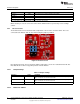
Hardware Description www.ti.com 2.7 2.7.1 RF Connections Radiated Testing (AP connection) By default the board ships with the RF signals routed to the on-board chip antenna. An on-board u.fl (Murata) connector provides a means to perform the testing in the lab using a compatible cable. Resistor mounted towards antenna path Murata Connector Figure 13. Radiated Testing Using Chip Antenna Resistor mounted towards U.FL Murata connector Figure 14. Board Set for Conducted Testing 2.8 2.8.
Software Examples 2.8.2 www.ti.com Revision History Table 10. Change Log PCB Revision Description Rev 3.0B Rev 3.1 • First baseline revision The • • • Rev 3.2 2.8.3 main changes pertain to the bill of materials (BOM) and the layout: Replaced the caps C23, C24 with ceramic ones to minimize leakage current R62 is made to DNP by default so that the jumper is used to measure the hibernate current Misc silk screen changes in order to clearly annotate components on the board.
Additional Resources www.ti.com 4.3 Download CCS, IAR Although the files can be viewed with any text editor, more can be done with the projects if they’re opened with a development environment like Code Composer Studio (CCS), IAR, or Energia. CCS and IAR are each available in a full version, or a free, code-size-limited version. The full out-of-box demo cannot be built with the free version of CCS or IAR (IAR Kickstart) due to the code size limit.
IMPORTANT NOTICE Texas Instruments Incorporated and its subsidiaries (TI) reserve the right to make corrections, enhancements, improvements and other changes to its semiconductor products and services per JESD46, latest issue, and to discontinue any product or service per JESD48, latest issue. Buyers should obtain the latest relevant information before placing orders and should verify that such information is current and complete.