
User's Manual
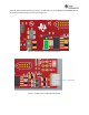

7.5.4 CC31XXEMUBOOSTJumperSettings
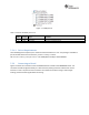
Table7‐4specifiesthejumperstobeinstalledwhilep a iringwiththeFTDIboard.Notethatjumpersnot
listedinTable7‐4remainopen.
No
Jumper
Settings
Notes
1
J4 (short)
Provide 3.3 V to the BoosterPack
2
J22 (short)
Provide 5.0 V to the BoosterPack
3
J3 (1-2)
Route the NWP logs to the Dual port also
Table7‐4:CC31XXEMUBOOSTJumperSettings
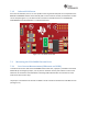
7.5.5 ConnectingtoaLaunchPadKit
TheCC3120RMBoosterPackmodulecanbedirectlyconnectedtoacompatibleLaunchPaddevelopment
kitusingthestandard2x20pinconnectors.Thejumpersettingsneededforthisconnectionarethesame
asthoseneededfortheEMUBOOSTboardasdescribedinsection7.5.4
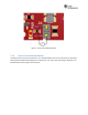
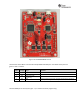
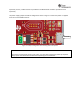
EnsurethatthePin1ofthe2x20pinsarealignedcorrectlybeforepairing.Figure7‐9illustratesthe
connectedsetup.NotethattheUSBcableisdirectlyconnectedtotheBoosterPackModule topowerit
only.Fordebugging,theUSBcableontheLaunchPadkitisalsorequired.
Figure7‐9:BOOSTXL‐CC3120MOD ConnectedtoMSP432LaunchPad
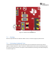
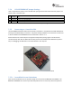
7.5.5.1 LaunchPadCurrentLimitations
SomeoftheLaunchPadkitsdonotprovideenoughcurrenttopowertheBOOSTXL‐CC3120MOD.The
BOOSTXL‐CC3120MODcanconsumeupto400mApeakfromthe3.3Vandmayneedtobepowered