
User's Manual
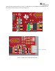
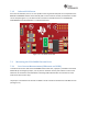
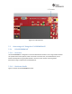
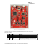
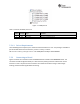
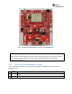
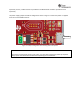

Figure7‐8:BOOSTXL‐CC3120MOD ConnectedtoCC31XXEMUBOOST
CAUTION
Alignpin1oftheboardstogetherusingthetrianglemarkingonthePCB.Anincorrectconnection
canpermanentlydestroytheboards.Ensurethatnon eoftheheaderpinsarebentbefore
connectingtheboards.
7.5.3 BOOSTXL‐CC3120MODJumperSettings
Table7‐3specifiesthejumperstobeinstalledontheBOOSTXL‐CC3120RMbeforepairingwiththe
EMUBOOSTboard
No
Jumper
Settings
Notes
1
J8 (1-2)
Power the BoosterPack from the EMU BOOST. The jumper shall be placed so that it is nearer to the edge of
the PCB.
3
J6 (short)
No current measurement.
Table7‐3:BOOSTXL‐CC3120MODJumperSettings