
User's Manual
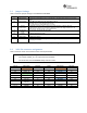
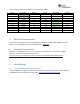
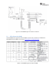
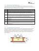
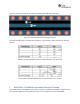

Table2‐5liststhe innerrowconnectorsofthe two 20‐pinheaders.
Pin
No
Signal Name
Direction Pin
No
Signal Name
Direction
P3.1
+5
V
IN P4.1
UNUSED
OUT
P3.2
GND
IN P4.2
UNUSED
OUT
P3.3
UNUSED
NA P4.3
UNUSED
NA
P3.4
UNUSED
NA P4.4
UART1_CTS
IN
P3.5
UNUSED
NA P4.5
UART1_RTS
OUT
P3.6
UNUSED
NA P4.6
UNUSED
NA
P3.7
UNUSED
NA P4.7
NWP_LOG_TX
OUT
P3.8
UNUSED
NA P4.8
WLAN_LOG_TX
OUT
P3.9
UNUSED
NA P4.9
UNUSED
IN
P3.10
UNUSED
NA P4.10
UNUSED
OUT
Table2‐5:BOOSTXL‐CC3120MODinnerrowpinconnectors
3. ElectricalCharacteristics
Forelectricalcharacteristics,seetheCC3120MODSimpleLink™ Wi‐FiCERTIFIED™NetworkProcessor
Internet‐of‐ThingsModuleSolutionforMCUApplicationsDatasheet.
4. AntennaCharacteristics
TheBOOSTXL‐CC3120MODcontainsanon‐chip ante nna.ForinformationontheantennaVSWR,
efficiency,andelectricalcharacteristicspleasesee:
http://ds.yuden.co.jp/TYCOMPAS/ap/detail.do?productNo=AH316M245001‐T&dataUnit=M
5. CircuitDesign
5.1 CC3120MODReferenceschematic
TheCC3120MODmainengineareareferenceschematicisshowinFigure5‐1below.ThefullBOOSTXL‐
CC3120MODreferenceschematiccanbefoundat:http://www.ti.com/lit/zip/swrc339.