
User manual
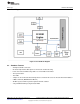

Hardware Description
www.ti.com
2.3 Connector and Jumper Descriptions
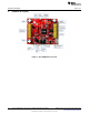
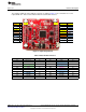
2.3.1 Push Buttons and LEDs
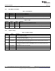
Table 1. Push Buttons
Reference Usage Comments
SW1 OOB Demo This is used as an input for the OOB demo.
SW2 RESET The use of this pin is optional. It resets the device to a known state.
SW3 nHIB This boots the device to the bootloader mode for flashing the firmware over a universal asynchronous
receiver/transmitter (UART).
Table 2. LEDs
Reference Colour Usage Comments
D5 RED PWR ON, when the 3.3 V power is provided to the board.
indication
D1 Yellow nRESET This LED indicates the state of the nRESET pin. If this LED is glowing, the device is functional.
D6 Green nHIB This LED indicates the state of the nHIB pin. When the LED is OFF, the device is in hibernate
state.
2.3.2 Jumper Settings
Table 3. Jumper Settings
Reference Usage Comments
J7 USB connector For powering the BoosterPack when connected with a LaunchPad. This is mandatory when using “Z”
devices (for example, CC3100HZ).
J8 Power selection Choose the power supply from the Lauchpad or the on-board USB.
J8 (1-2) power from MCU LaunchPad
J8 (2-3) power from on-board USB using 3.3 V LDO
J6 Current For Hibernate and LPDS currents, connect an ammeter across J26 : Range (< 500 µA)
measurement For Active current, mount a 0.1 Ω resistor on R42 and measure the voltage across the 0.1 Ω resistor
using a voltmeter (range (< 50 mV peak-peak)).
J5 Reserved Closed: nHIB is pulled to VCC using 10K
Open: nHIB pin is floating and is driven from EMUBOOST. (On Rev 3.3 and earlier, this was used to
control GPIO_12)
J10, J9 BoosterPack 2x10 pins each connected to the LaunchPad.
header
J3 RF Test Murata connector (MM8030-2610) for production line tests.
J2 RF Test U.FL connector for conducted testing in the lab.
8
CC3100 SimpleLink™ Wi-Fi
®
and IoT Solution BoosterPack Hardware SWRU371B–June 2014–Revised January 2015
Submit Documentation Feedback
Copyright © 2014–2015, Texas Instruments Incorporated