
User manual

www.ti.com
Hardware Description
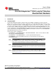
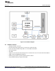
2.1 Block Diagram
Figure 2. CC3100 Block Diagram
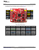
2.2 Hardware Features
• 2x20 pin stackable connectors
• On-board chip antenna with option for U.FL-based conducted testing
• Power from on-board LDO using USB or 3.3 V from MCU LaunchPad
• Three push buttons
• Two LEDs
• Jumper for current measurement with provision to mount 0.1R resistor for measurement with voltmeter
• 8 Mbit serial flash (M25PX80 from Micron)
• 40 MHz crystal, 32 KHz crystal and optional 32 KHz oscillator
• 4-layer PCB with 6 mil spacing and track width
7
SWRU371B–June 2014–Revised January 2015 CC3100 SimpleLink™ Wi-Fi
®
and IoT Solution BoosterPack Hardware
Submit Documentation Feedback
Copyright © 2014–2015, Texas Instruments Incorporated