
User manual

www.ti.com
List of Figures
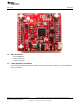
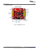
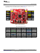
1 CC3100BOOST Front Side................................................................................................. 6
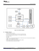
2 CC3100 Block Diagram ..................................................................................................... 7
3 Signal Assignments.......................................................................................................... 9
4 3.3 V Power From MCU................................................................................................... 11
5 Feed USB on the BoosterPack (if the LaunchPad cannot source 5 V on 20-pin connector) .................... 11
6 3.3 V Power From LDO ................................................................................................... 12
7 Feed USB on the BoosterPack (always while using the on-board LDO) ........................................... 12
8 Low Current Measurement................................................................................................ 13
9 Active Current Measurement ............................................................................................. 13
10 Connectors on the Board.................................................................................................. 14
11 Radiated Mode (Left) vs Conducted Mode (Right) .................................................................... 14
12 CC31XXEMUBOOST Board.............................................................................................. 15
13 Portable Devices ........................................................................................................... 16
14 The CC3100BOOST Connected to the EMUBOOST ................................................................. 17
15 CC3100BP connected to MSP430F5529 LaunchPad................................................................. 18
16 Jumper Settings When Used With LaunchPad......................................................................... 19
List of Tables
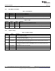
1 Push Buttons ................................................................................................................. 8
2 LEDs........................................................................................................................... 8
3 Jumper Settings.............................................................................................................. 8
4 Outer Row Connectors...................................................................................................... 9
5 Inner Row Connectors..................................................................................................... 10
6 Ports Available on J6 ...................................................................................................... 15
7 Ports Available on J5 ...................................................................................................... 16
8 CC3100BOOST Jumper Settings ........................................................................................ 17
9 EMUBOOST Jumper Settings ............................................................................................ 18
10 Hardware Change Log..................................................................................................... 20
3
SWRU371B–June 2014–Revised January 2015 List of Figures
Submit Documentation Feedback
Copyright © 2014–2015, Texas Instruments Incorporated