
User manual

Connecting to the PC Using EMUBOOST
www.ti.com
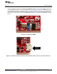
3.4 Jumper Settings on the EMUBOOST
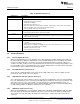
Table 9 specifies the jumpers to be installed while pairing with the FTDI board.
Table 9. EMUBOOST Jumper Settings
Jumper
No Settings Notes
1 J4 (short) Provide 3.3 V to the BoosterPack
2 J22 (short) Provide 5.0 V to the BoosterPack
3 J3 (1-2) Route the NWP logs to the Dual port also
The rest of the jumpers can remain open.
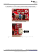
4 Connecting to a LaunchPad
The CC3100 BoosterPack can be directly connected to a compatible LaunchPad using the standard 2x20
pin connectors. The jumper settings needed for this connection are the same as that needed for the
EMUBOOST board as described in Section 3.4.
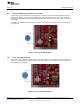
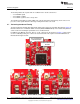
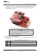
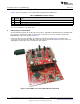
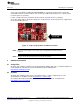
Ensure that the Pin1 of the 2x20 pins are aligned correctly before pairing. Figure 15 illustrates the
connected setup. Note that the USB cable is directly connected to the BoosterPack to power it only. For
debugging, the USB cable on the LaunchPad is also required.
Figure 15. CC3100BP connected to MSP430F5529 LaunchPad
18
CC3100 SimpleLink™ Wi-Fi
®
and IoT Solution BoosterPack Hardware SWRU371B–June 2014–Revised January 2015
Submit Documentation Feedback
Copyright © 2014–2015, Texas Instruments Incorporated