
User manual
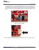
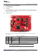
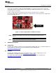

Murata connector for
RF tests
U.FL connector for
external antenna
Hardware Description
www.ti.com
2.6 Clocking
The board provides two crystals and one oscillator for the clocks to the device:
• Y1: a 40-MHz crystal
• Y2: a 32KHz oscillator
• Y3: a 32KHz crystal used as a sleep clock
The 32-kHz crystal allows for lower LPDS sleep currents than other low-frequency clock sources. The
presence of the crystal allows the full range of low-power modes to be used.
2.7 Performing Conducted Testing
The BoosterPack by default ships with the RF signal connected to the on-board chip antenna. Figure 10
illustrates that there is a miniature UMC connector (Murata MM8030-2610) on the board's RF path that
can be used for measuring the performance in a conducted mode.
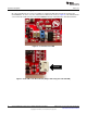
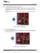
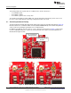
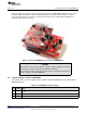
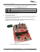
In addition to the Murata connector, there is a U.FL connector on the board (see Figure 11) that can be
used for conducting testing or to connect an external antenna. This requires a board modification, as
illustrated in the figures below.
Figure 10. Connectors on the Board
Figure 11. Radiated Mode (Left) vs Conducted Mode (Right)
14
CC3100 SimpleLink™ Wi-Fi
®
and IoT Solution BoosterPack Hardware SWRU371B–June 2014–Revised January 2015
Submit Documentation Feedback
Copyright © 2014–2015, Texas Instruments Incorporated