
User manual

Hardware Description
www.ti.com
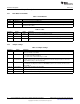
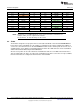
Table 5. Inner Row Connectors
Pin No Signal Name Direction Pin No Signal Name Direction
P3.1 +5 V IN P4.1 UNUSED OUT
P3.2 GND IN P4.2 UNUSED OUT
P3.3 UNUSED NA P4.3 UNUSED NA
P3.4 UNUSED NA P4.4 UART1_CTS IN
P3.5 UNUSED NA P4.5 UART1_RTS OUT
P3.6 UNUSED NA P4.6 UNUSED NA
P3.7 UNUSED NA P4.7 NWP_LOG_TX OUT
P3.8 UNUSED NA P4.8 WLAN_LOG_TX OUT
P3.9 UNUSED NA P4.9 UNUSED IN
P3.10 UNUSED NA P4.10 UNUSED OUT
NOTE: All signals are 3.3 V CMOS 400mA logic levels and are referred w.r.t. CC3100 IC. For
example, UART1_TX is an output from the CC3100.
For the SPI lines, the CC3100 always acts like a slave.
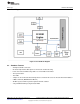
2.4 Power
The board is designed to accept power from a connected LaunchPad or from the CC3100EMUBOOST
board. Some of the LaunchPads are not capable of sourcing the peak current requirements of Wi-Fi. In
such a case, the USB connector on the CC3100BOOST can be used to aid the peak current. The use of
Schottky diodes ensure that the load sharing happens between the USB connectors on the LaunchPad
and the BoosterPack without any board modifications.
Also the 3.3 V power can be sourced from the LaunchPad or from the 3.3 V LDO on the board. This is
done by using jumper J8. In the case where the LaunchPad is not able to source the 3.3 V up to 350mA,
then the J8 needs to be configured to work from the on-board LDO.
10
CC3100 SimpleLink™ Wi-Fi
®
and IoT Solution BoosterPack Hardware SWRU371B–June 2014–Revised January 2015
Submit Documentation Feedback
Copyright © 2014–2015, Texas Instruments Incorporated