CC3100 SimpleLink™ Wi-Fi® and IoT Solution BoosterPack Hardware User's Guide Literature Number: SWRU371B June 2014 – Revised January 2015
Contents 1 2 3 4 Introduction ......................................................................................................................... 4 1.1 CC3100 BOOST.......................................................................................................... 4 1.2 What Is Included 1.3 FCC/IC Regulatory Compliance ........................................................................................ 5 ..............................................................................
www.ti.com List of Figures 1 CC3100BOOST Front Side ................................................................................................. 6 2 CC3100 Block Diagram ..................................................................................................... 7 3 Signal Assignments.......................................................................................................... 9 4 3.3 V Power From MCU .........................................................................
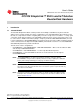
User's Guide SWRU371B – June 2014 – Revised January 2015 CC3100 SimpleLink™ Wi-Fi® and IoT Solution BoosterPack Hardware 1 Introduction 1.1 CC3100 BOOST The CC3100 SimpleLink™ Wi-Fi® solution provides the flexibility to add Wi-Fi to any microcontroller (MCU). This user guide explains the various configurations of the CC3100 hardware BoosterPack™. This internet on a chip solution contains everything that you need to easily create IoT solutions – security, quick connection, cloud support and more.
Introduction www.ti.com 1.2 What Is Included • • • 1.3 1x CC3100BOOST 1x Micro USB cable 1x Quick start guide FCC/IC Regulatory Compliance The CC3100 SimpleLink Wi-Fi and IoT Solution BoosterPack Hardware is FCC Part 15 and IC ICES-003 Class A Compliant.
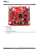
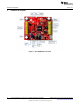
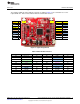
Hardware Description 2 www.ti.com Hardware Description Figure 1.
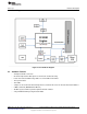
Hardware Description www.ti.com 2.1 Block Diagram Figure 2. CC3100 Block Diagram 2.2 Hardware Features • • • • • • • • • 2x20 pin stackable connectors On-board chip antenna with option for U.FL-based conducted testing Power from on-board LDO using USB or 3.3 V from MCU LaunchPad Three push buttons Two LEDs Jumper for current measurement with provision to mount 0.
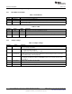
Hardware Description 2.3 www.ti.com Connector and Jumper Descriptions 2.3.1 Push Buttons and LEDs Table 1. Push Buttons Reference Usage SW1 OOB Demo SW2 RESET SW3 nHIB Comments This is used as an input for the OOB demo. The use of this pin is optional. It resets the device to a known state. This boots the device to the bootloader mode for flashing the firmware over a universal asynchronous receiver/transmitter (UART). Table 2.
Hardware Description www.ti.com 2.3.3 2x20 Pin Connector Assignment The signal assignment on the 2x20 pin connector is shown in Figure 3. The convention of J1..J4 is replaced with P1…P4 to avoid confusion with the actual board reference. P4 P2 P1 P3 P1 P3 P4 P2 VCC(3.
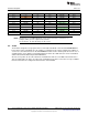
Hardware Description www.ti.com Table 5. Inner Row Connectors Pin No Signal Name Direction Pin No Signal Name Direction P3.1 +5 V IN P4.1 UNUSED OUT P3.2 GND IN P4.2 UNUSED OUT P3.3 UNUSED NA P4.3 UNUSED NA P3.4 UNUSED NA P4.4 UART1_CTS IN P3.5 UNUSED NA P4.5 UART1_RTS OUT P3.6 UNUSED NA P4.6 UNUSED NA P3.7 UNUSED NA P4.7 NWP_LOG_TX OUT P3.8 UNUSED NA P4.8 WLAN_LOG_TX OUT P3.9 UNUSED NA P4.9 UNUSED IN P3.10 UNUSED NA P4.
Hardware Description www.ti.com 2.4.1 Power From the LaunchPad or CC3100EMUBOOST The most common scenario is to power the CC3100BOOST from the connected LaunchPad. In this case, the LaunchPad provides 3.3 V to the BoosterPack for its operation (see Figure 4). In addition to the 3.3 V, some LaunchPads provide a 5 V from the USB (see Figure 5), which is used to drive a 3.3 V LDO on the BoosterPack. In case the LaunchPad is not able to provide the 5V (for e.g.
Hardware Description 2.4.2 www.ti.com On-Board LDO Power Supply On some LaunchPads, the 3.3 V is not capable of sourcing the 350 mA peak current needed for the CC3100BOOST. In such a case, the on-board 3.3 V LDO can be used (see Figure 6). This LDO would be sourced from the USB connector on the CC3100BOOST and the LaunchPad in a shared load manner. Figure 6. 3.3 V Power From LDO USB PWR Figure 7.
Hardware Description www.ti.com 2.5 2.5.1 Measure the CC3100 Current Draw Low Current Measurement (Hibernate and LPDS) To measure the current draw of the CC3100 device, a jumper is provided on the board labeled J6. By removing this jumper, you can place an ammeter into this path and the current can be observed. This method is recommended for measuring LPDS and hibernate currents that are of the order of few 10s of micro amps.
Hardware Description 2.6 www.ti.com Clocking The board provides two crystals and one oscillator for the clocks to the device: • Y1: a 40-MHz crystal • Y2: a 32KHz oscillator • Y3: a 32KHz crystal used as a sleep clock The 32-kHz crystal allows for lower LPDS sleep currents than other low-frequency clock sources. The presence of the crystal allows the full range of low-power modes to be used. 2.
Connecting to the PC Using EMUBOOST www.ti.com 3 Connecting to the PC Using EMUBOOST 3.1 CC31XXEMUBOOST 3.1.1 Overview The CC31XXEMUBOOST is designed to connect the BoosterPack to a PC using a USB connection. This updates the firmware patches, which are stored in the serial flash, on the BoosterPack; and in software development using SimpleLink Studio. 3.1.2 Hardware Details Figure 12. CC31XXEMUBOOST Board The board has two FTDI ICs to enumerate multiple COM and D2XX ports.
Connecting to the PC Using EMUBOOST www.ti.com The first COM port in the list is used for the Flash programming. Figure 13. Portable Devices Table 7. Ports Available on J5 3.1.3 Port Number Port Type Usage Comments 1 VCP RT3 Used for TI internal debug only. 2 VCP MAC logger Used for TI internal debug only. Driver Requirements The FTDI Debug board requires you to install the associated drivers on a PC.
Connecting to the PC Using EMUBOOST www.ti.com 3.2 Connecting the Boards Figure 14 shows the connection of the CC3100 BoosterPack to the EMUBOOST Board. The connectors should be aligned carefully as it does not have polarity protection and the sFlash can be erased as a result. The pins #1 of the connectors are marked on the board using a small triangle marking; these should be aligned while connecting. Figure 14.
Connecting to the PC Using EMUBOOST 3.4 www.ti.com Jumper Settings on the EMUBOOST Table 9 specifies the jumpers to be installed while pairing with the FTDI board. Table 9. EMUBOOST Jumper Settings No Jumper Settings Notes 1 J4 (short) Provide 3.3 V to the BoosterPack 2 J22 (short) Provide 5.0 V to the BoosterPack 3 J3 (1-2) Route the NWP logs to the Dual port also The rest of the jumpers can remain open.
Connecting to a LaunchPad www.ti.com 4.1 LaunchPad Current Limitation Some of the LaunchPads, including the MSP430FRAM, do not provide enough current to power the CC3100 BoosterPack. The BoosterPack can consume up to 400 mA peak from the 3.3 V and it may be needed to power is separately. For this, a USB connector is provided on the BoosterPack to provide the 3.3 V separately. The power supply jumpers should be configured as shown in Figure 16 when the power is supplied from the on-board USB connector.
Additional Information 5.3 www.ti.com Hardware Change Log Table 10. Hardware Change Log PCB Revision 5.4 5.4.1 Description Rev 2.0B • First release Rev 3.0A • • • • • • • Added push button for nHIB Added Murata Connector for RF test Added LED for nRESET Routed the VDD_FLASH to 3.3 V Moved the 100uF cap from VCC_BRD to VBAT_CC. Changed cap to 100uF ceramic from Tantalum Removed 0.1 Ohm resistor for current measurement by default Removed RS232 UART connection by default Rev 3.
Revision History www.ti.com Revision History Changes from A Revision (August 2014) to B Revision ................................................................................................ Page • Added Board Modification for LPDS mode section. ................................................................................. 20 Revision History Changes from Original (June 2014) to A Revision .........................................................................................................
Revision History www.ti.com STANDARD TERMS AND CONDITIONS FOR EVALUATION MODULES (continued) CAUTION This device complies with part 15 of the FCC Rules. Operation is subject to the following two conditions: (1) This device may not cause harmful interference, and (2) this device must accept any interference received, including interference that may cause undesired operation.
Revision History www.ti.com STANDARD TERMS AND CONDITIONS FOR EVALUATION MODULES (continued) Conformément à la réglementation d'Industrie Canada, le présent émetteur radio peut fonctionner avec une antenne d'un type et d'un gain maximal (ou inférieur) approuvé pour l'émetteur par Industrie Canada. Dans le but de réduire les risques de brouillage radioélectrique à l'intention des autres utilisateurs, il faut choisir le type d'antenne et son gain de sorte que la puissance isotrope rayonnée équivalente (p.i.
Revision History www.ti.com STANDARD TERMS AND CONDITIONS FOR EVALUATION MODULES (continued) 4.3.1 User shall operate the EVM within TI’s recommended specifications and environmental considerations stated in the user guide, other available documentation provided by TI, and any other applicable requirements and employ reasonable and customary safeguards.
Revision History www.ti.com STANDARD TERMS AND CONDITIONS FOR EVALUATION MODULES (continued) 8.1 General Limitations. IN NO EVENT SHALL TI BE LIABLE FOR ANY SPECIAL, COLLATERAL, INDIRECT, PUNITIVE, INCIDENTAL, CONSEQUENTIAL, OR EXEMPLARY DAMAGES IN CONNECTION WITH OR ARISING OUT OF THESE TERMS ANDCONDITIONS OR THE USE OF THE EVMS PROVIDED HEREUNDER, REGARDLESS OF WHETHER TI HAS BEEN ADVISED OF THE POSSIBILITY OF SUCH DAMAGES.
IMPORTANT NOTICE Texas Instruments Incorporated and its subsidiaries (TI) reserve the right to make corrections, enhancements, improvements and other changes to its semiconductor products and services per JESD46, latest issue, and to discontinue any product or service per JESD48, latest issue. Buyers should obtain the latest relevant information before placing orders and should verify that such information is current and complete.