
User's Manual
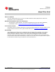
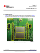
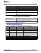

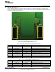
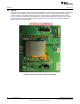
Table Of Contents

SWRU326-002
www.ti.com
EM Board Bottom View
2.2 EM Board Bottom View
The two EM board mating connectors J6 and J7 connect to the host platform and are mounted on the
bottom of the EM board, as shown in Figure 2-2. Table 2-5 and Table 2-6 describe the signals brought out
from these two EM mating connectors.
Figure 2-2. CC3000 EM Board Bottom View
Table 2-5. Header J6 of CC3000 EM Board Bottom View
J6 Pin Pin Name Module Pin Type Description
1 GND – Ground
5 Reserved – Reserved
10 VBAT_SW_EN Input Active-high enable signal from the host device
12 WL_SPI_IRQ Output Host interface SPI interrupt request
14 WL_SPI_CS Input Host interface SPI CS
16 WL_SPI_CLK Input Host interface SPI clock input
18 WL_SPI_DIN Input Host Interface SPI data input
19 GND – Ground
20 WL_SPI_DOUT Output Host interface SPI data output
Table 2-6. J7 of CC3000 EM Board Bottom View
J7 Pin Pin Name Module Pin Type Description
2 GND – Ground
7 VBAT_IN Power In Battery voltage input to the module
9 VBAT_IN Power In Battery voltage input to the module
15 Reserved – Reserved
9
SWRU326–November 2012 CC3000 EM Board
Submit Documentation Feedback
Copyright © 2012, Texas Instruments Incorporated