
User's Manual
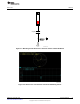
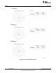

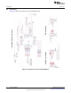
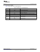
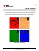

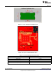

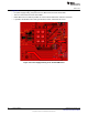
Table Of Contents

SWRU326-013
www.ti.com
Table 3-1. Module Layout Guidelines
Reference
(1)
Guideline Description
1 The proximity of ground vias must be close to the pad.
2 Signal traces must not be run underneath the module on the layer where the module is mounted.
3 Have a complete ground pour in layer 2 for thermal dissipation.
4 Have a solid ground plane and ground vias under the module for stable system and thermal dissipation.
5 Increase the ground pour in the first layer and have all of the traces from the first layer on the inner
layers, if possible.
6 Signal traces can be run on a third layer under the solid ground layer, which is below the module
mounting layer.
(1)
See Figure 3-2.
Figure 3-2. Module Layout Guidelines
Figure 3-3 shows the trace design for the PCB. A 50-Ω impedance match on the trace to the antenna
should be used. Also, 50-Ω traces are recommended for the PCB layout. Table 3-2 lists the distances
shown in Figure 3-3. Figure 3-4 shows layer 1 with the trace to the antenna over ground layer 2. Table 3-3
and Figure 3-5 describe instances of good layout practices for the antenna and RF trace routing.
17
SWRU326–November 2012 Layout Guidelines
Submit Documentation Feedback
Copyright © 2012, Texas Instruments Incorporated