
User manual


I/O Control Registers
www.ti.com
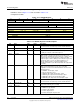
11.11.2.7 IOCFG6 Register (Offset = 18h) [reset = X]
IOCFG6 is shown in Figure 11-14 and described in Table 11-17.
Configuration of DIO6
Figure 11-14. IOCFG6 Register
31 30 29 28 27 26 25 24
RESERVED HYST_EN IE WU_CFG IOMODE
R-X R/W-X R/W-X R/W-X R/W-X
23 22 21 20 19 18 17 16
RESERVED EDGE_IRQ_EN EDGE_DET
R/W-X R/W-X R/W-X
15 14 13 12 11 10 9 8
RESERVED PULL_CTL SLEW_RED IOCURR IOSTR
R-X R/W-3h R/W-X R/W-X R/W-X
7 6 5 4 3 2 1 0
RESERVED PORT_ID
R-X R/W-X
Table 11-17. IOCFG6 Register Field Descriptions
Bit Field Type Reset Description
31 RESERVED R X
Software should not rely on the value of a reserved. Writing any
other value than the reset value may result in undefined behavior.
30 HYST_EN R/W X
0: Input hysteresis disable 1: Input hysteresis enable
29 IE R/W X
0: Input disabled 1: Input enabled Note: If IO is configured for AUX
ie. PORT_ID = 0x08, the enable will be ignored.
28-27 WU_CFG R/W X
If DIO is configured GPIO or non-AON peripheral signals, i.e.
PORT_ID 0x00 or >0x08: 00: No wake-up 01: No wake-up 10:
Wakes up from shutdown if this pad is going low. 11: Wakes up from
shutdown if this pad is going high. If IO is configured for AON
peripheral signals or AUX ie. PORT_ID 0x01-0x08, this register only
sets wakeup enable or not. 00, 01: Wakeup disabled 10, 11:
Wakeup enabled Polarity is controlled from AON registers.
Note:When the MSB is set, the IOC will deactivate the output enable
for the DIO.
26-24 IOMODE R/W X
IO Mode N/A for IO configured for AON periph. signals and AUX ie.
PORT_ID 0x01-0x08 AUX has its own open_source/drain
configuration. 0x2: Reserved. Undefined behavior. 0x3: Reserved.
Undefined behavior.
0h = NORMAL : Normal input / output
1h = INV : Inverted input / ouput
4h = OPENDR : Open Drain, Normal input / output
5h = OPENDR_INV : Open Drain Inverted input / output
6h = OPENSRC : Open Source Normal input / output
7h = OPENSRC_INV : Open Source Inverted input / output
23-19 RESERVED R/W X
Software should not rely on the value of a reserved. Writing any
other value than the reset value may result in undefined behavior.
18 EDGE_IRQ_EN R/W X
0: No interrupt generation 1: Enable interrupt generation for this IO
(Only effective if EDGE_DET is enabled)
17-16 EDGE_DET R/W X
Enable generation of edge detection events on this IO
0h = NONE : No edge detection
1h = Negative edge detection
2h = Positive edge detection
3h = Positive and negative edge detection
908
I/O Control SWCU117A–February 2015–Revised March 2015
Submit Documentation Feedback
Copyright © 2015, Texas Instruments Incorporated