
User manual


I/O Control Registers
www.ti.com
11.11.1.4 IOCLATCH Register (Offset = Ch) [reset = X]
IOCLATCH is shown in Figure 11-6 and described in Table 11-8.
IO Latch Control Controls transparency of all latches holding I/O or configuration state from the MCU IOC
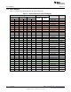
Figure 11-6. IOCLATCH Register
31 30 29 28 27 26 25 24 23 22 21 20 19 18 17 16
RESERVED
R-X
15 14 13 12 11 10 9 8 7 6 5 4 3 2 1 0
RESERVED EN
R-X R/W-
1h
Table 11-8. IOCLATCH Register Field Descriptions
Bit Field Type Reset Description
31-1 RESERVED R X
Software should not rely on the value of a reserved. Writing any
other value than the reset value may result in undefined behavior.
0 EN R/W 1h
Controls latches between MCU IOC and AON_IOC. The latches are
transparent by default. They must be closed prior to power off the
domain(s) controlling the IOs in order to preserve IO values on
external pins.
0h = Latches are static, meaning the current value on the IO pin is
frozen by latches and kept even if GPIO module or a peripheral
module is turned off
1h = Latches are transparent, meaning the value of the IO is directly
controlled by the GPIO or peripheral value
880
I/O Control SWCU117A–February 2015–Revised March 2015
Submit Documentation Feedback
Copyright © 2015, Texas Instruments Incorporated