
User manual


Pins
MCU IOC
AON PERIPH
Peripherals
Edge
Detect
tdit
tdot
toe_nt
tPin configt
taonpadselt
taon padent
tpin_ctrlt
tdit
tdot
toe_nt
tdit
tdot
toe_nt
MCU Latch
AUX
Latch
GPIO
AON Event
MUX
CFG
AON/AUX MUX
AON Peripherals
tiet
MCU Event
AON
AUX
MCU
TMS Pin
TMS
CTRL
DEBUG
SS
AON BATMON
bmon_level
Latch
MCU AONIFtcfgt
AON IOC
...
AUX
tdot
toe_nt
tiet
IRQ
tauxent
tdit
Introduction
www.ti.com
11.1 Introduction
The I/O controller configures pins and map peripheral signals to physical pins (DIOx) on the CC26xx
package. This chapter explains the IOC implementation and gives a few examples on how to map
peripheral functions to pins chosen by the user.
Several similar terms that can cause confusion follow:
• Pins are, in this context, defined as everything from the physical metals pads on the outside of the
package, to the last internal analog stage that drives and sense input signals on these lines (see
Figure 11-2.
• PORTID is the number for a peripheral function.
• GPIO is a peripheral function with the PORTID of 0x0.
• DIO (DIO0 to DIO31) are the logic names for the different I/O pins on the specific package.
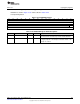
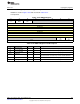
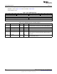
Table 11-1 provides the mappings between DIO and pin for the different packages. Eight of these
DIOs also have analog capabilities.
11.2 IOC Overview
Figure 11-1 shows a general overview.
The IOC module consists of two main submodules:
• Microcontroller unit IOC (MCU IOC) configures the peripheral ports to the user-defined pins.
• Always-on IOC (AON IOC) module handles SPI-S, JTAG, 32-kHz clock, and AUX signals.
The always-on peripherals (AON Peripherals) can operate even when the MCU IOC is powered down, but
they run at the 32 kHz clock low speed clock, except for the SPI-S module that runs at an externally
supplied clock (SCK). This allows the device to operate at very low power levels while still being able to
maintain active operation of these peripheral functions. When configured correctly, the AON IOC ensures
that output levels of all the I/O’s remain unchanged when the MCU power domain, which includes the
MCU IOC, is powered down (for more details see Section 11.5, AON IOC State Latching When Powering
Off the MCU Domain).
Figure 11-1. IOC Overview (Simplified)
868
I/O Control SWCU117A–February 2015–Revised March 2015
Submit Documentation Feedback
Copyright © 2015, Texas Instruments Incorporated