
User manual


AES Cryptoprocessor Overview
www.ti.com
The AES engine has a 32-bit write interface for input data to be encrypted or decrypted, and a 32-bit read
interface for result data and tag. The write interface of the AES module collects 32-bit data into a 128-bit
input block (AES block size) and when a full block is received, the AES calculation for the received block
is started. When receiving the last word of the last block, the DMAC and master controller generate a
"data done" signal to the crypto engine. The mode, length of the message, and optional parameters are
programmed using the target interface.
On the TCM side, the key store module immediately accepts all data without delay cycles, while the hash
and crypto modules operate on a data block boundary. Processing the boundary takes a number of clock
cycles. Special handshake signals are used between the DMAC and crypto modules:
• A data input request is sent to the DMA inbound channel (channel 0) when the crypto module can
accept the next data block.
• A data output request is sent to the DMA output channel (channel 1) when the crypto module has the
next block of data or tag available, after processing or hash module has a digest available.
• Both channels send an acknowledge when the DMA operation has started, channel transfer done,
when a block has been transmitted and the channel done, or when all data is transmitted.
10.1.4.3.2 Supported DMA Operations
With each data request from the crypto engine, the DMAC requests a transfer from the AHB master. The
transfer size is at most the block size of the corresponding algorithm. This block size depends on the
selected algorithm in the master control module.
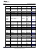
A summary of the supported DMAC operations is shown in Table 10-2. The module refers to the selected
module in the master control module. TAG enable indicates whether the TAG bit is set in the master
control configuration register.
Table 10-2. Supported DMAC Operations
Module Incoming Data Stream (for channel 0) Outcoming Data Stream (for channel 1)
Source Destination Source Destination
Key store External memory location Key store RAM - -
RAM (Authentication data only) AES See
(1)
See
(1)
Crypto External memory location AES AES External memory location
See
(2)
See
(2)
AES (TAG enabled) External memory location
(1)
TAG is transferred via the slave interface or transferred with a separate DMA.
(2)
Data is transferred via another DMA, that has been executed before
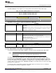
10.1.4.4 Master Control and Select
The master control module synchronizes the DMA operations and the cryptographic module handshake
signals. In this module, the crypto algorithm is selected and the DMA burst sizes are defined. Once the
complete encryption operation is complete, an interrupt is asserted.
NOTE: For authentication operations, the interrupt is only asserted if the authentication result is
available.
The AES module also provides an interrupt to indicate that the input DMA transfer has completed. This
interrupt is primarily used to determine the end of an AAD data DMA transfer (AES-CCM), which is
typically set up as separate input data transfer.
804
Cryptography SWCU117A–February 2015–Revised March 2015
Submit Documentation Feedback
Copyright © 2015, Texas Instruments Incorporated