
User manual


DMA Controller
Channel 0
(Inbound)
external DMA port
Control registers
Bus master adapter
(AHB)
Port control
DMA req/ack
DMA src addr
DMA dest addr
DMA length
Peripheral req/
ack/burst_size
TCM
DMA active
transfer
Crypto engines module
TCM slave
ext DMA
params
req/
ack
conf./
status
Port error
ext DMA
params
Arbiter
Peripheral req/
ack/burst_size
Master control
Bus slave adapter
(AHB)
status
Channel 1
(Outbound)
Block/channel
done
ack
Block/channel
done
Crypto engine Hash engine Key store
conf./
status
Interrupts
AES Cryptoprocessor Overview
www.ti.com
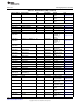
Table 10-1. Detailed Memory Map (continued)
Physical Address Register Name Type Reset Value Remark Link
0x4002 47F8 HWOPT R 0x0201 0093 Type and Options
Register
0x4002 47FC HWVER R 0x9110 8778 Version Register Section 10.2.1.40
Unspecified addresses are reserved and should not be written and ignored on a read.
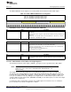
10.1.4.3 DMA Controller
Figure 10-1 shows the DMA Controller and its integration in the AES module.
Figure 10-1. DMA Controller and Its Integration
The DMA controller (DMAC) of the AES module controls the data transfer requests to the AHB Master
adapter, which transfers data to and from the AES engines and key store area.
The required parameters for proper functioning of the AHB master interface port are defined in the
[DMABUSCFG] register. The default configuration of this register configures fixed length transfers and
maximum burst size of 4 bytes. As a result, only nonsequential single transfers are performed on the AHB
bus.
The [DMASTAT] and [DMAPORTERR] registers provide the actual state of each DMA channel and
individual AHB port errors. A port error aborts operations on all serviced channels and prevents further
transfers using that port, until the error is cleared by writing to the [DMASWRESET] register.
802
Cryptography SWCU117A–February 2015–Revised March 2015
Submit Documentation Feedback
Copyright © 2015, Texas Instruments Incorporated