
User manual


AES Cryptoprocessor Overview
www.ti.com
NOTE: The CC26xx does not support burst or non-sequential transfers through internal
interconnect. The [DMABUSCFG] register must not be changed for proper operation.
10.1.3.3 Interrupts
The AES module has two interrupt outputs; both are driven from the master control module and are
controlled by the respective registers (see Section 10.1.4.4.3, Software Reset)
To enable interrupts for the AES engine, IRQTYPE.EN must be set and the interrupt source configured in
the IRQEN register.
The [IRQCLR] register is available to clear an interrupt output and error-status bit. The [IRQSET] register
provides the software a way to test the interrupt connections, and should be used for debugging only.
The [IRQSTAT] register provides the status of the two interrupts along with error status messages. The
error status bits are asserted once they are detected, and typically the value of DMA_BUS_ERR and
KEY_ST_WR_ERR signals are valid after assertion of the RESULT_AVAIL. The KEY_ST_RD_ERR bit is
valid after triggering the key store module to read a key from memory and providing it to the AES engine.
An interrupt RESULT_AVAIL is activated when an operation that uses DMA is finished. The signal asserts
when both the DMA and internal module are in the idle state.
Another interrupt DMA_IN_DONE is activated when only the input DMA is finished and is intended for
debugging purpose.
NOTE: Interrupt outputs are not triggered for operations where the DMA is not used.
10.1.4 Module Description
10.1.4.1 Introduction
This section describes some accessible registers, internal interfaces, and module functionality. The
registers and functionality are discussed per submodule. For complete information on the module
registers, see , Register Section.
10.1.4.2 Module Memory Map
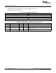
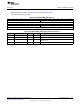
Table 10-1. Detailed Memory Map
Physical Address Register Name Type Reset Value Remark Link
DMA Controller Registers
0x4002 4000 DMACH0CTL R/W 0x0000 0000 Channel 0 control
Section 10.2.1.1
register
0x4002 4004 DMACH0EXTADDR R/W 0x0000 0000 Channel 0 external
Section 10.2.1.2
address
0x4002 400C DMACH0LEN R/W 0x0000 0000 Channel 0 DMA
Section 10.2.1.3
length
0x4002 4018 DMASTAT R 0x0000 0000 DMAC Status Section 10.2.1.4
0x4002 401C DMASWRESET W 0x0000 0000 DMAC Software
Section 10.2.1.5
reset
0x4002 4020 DMACH1CTL R/W 0x0000 0000 Channel 1 control
Section 10.2.1.6
register
0x4002 4024 DMACH1EXTADDR R/W 0x0000 0000 Channel 1 external
Section 10.2.1.7
address
0x4002 402C DMACH1LEN R/W 0x0000 0000 Channel 1 DMA
Section 10.2.1.8
length
0x4002 4078 DMABUSCFG R/W 0x0000 6000 Master run-time
Section 10.2.1.9
parameters
800
Cryptography SWCU117A–February 2015–Revised March 2015
Submit Documentation Feedback
Copyright © 2015, Texas Instruments Incorporated