
User manual


Customer Configuration (CCFG)
www.ti.com
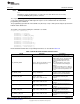
9.1.1.3 MODE_CONF Register (Offset = FB4h) [reset = FFFFFFFFh]
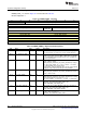
MODE_CONF is shown in Figure 9-3 and described in Table 9-4.
Mode Configuration 0
Figure 9-3. MODE_CONF Register
31 30 29 28 27 26 25 24
VDDR_TRIM_SLEEP_DELTA DCDC_RECHA DCDC_ACTIVE VDDR_EXT_L VDDS_BOD_L
RGE OAD EVEL
R/W-Fh R/W-1h R/W-1h R/W-1h R/W-1h
23 22 21 20 19 18 17 16
SCLK_LF_OPTION RESERVED RTC_COMP XOSC_FREQ XOSC_CAP_M HF_COMP
OD
R/W-3h R/W-1h R/W-1h R/W-3h R/W-1h R/W-1h
15 14 13 12 11 10 9 8
XOSC_CAPARRAY_DELTA
R/W-FFh
7 6 5 4 3 2 1 0
VDDR_CAP
R/W-FFh
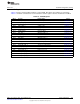
Table 9-4. MODE_CONF Register Field Descriptions
Bit Field Type Reset Description
31-28 VDDR_TRIM_SLEEP_DE R/W Fh
Signed delta value to apply to the VDDR_TRIM_SLEEP target,
LTA
minus one. See FCFG1:VOLT_TRIM.VDDR_TRIM_SLEEP_H. 0x8
(-8) : Delta = -7 ... 0xF (-1) : Delta = 0 0x0 (0) : Delta = +1 ... 0x7
(7) : Delta = +8
27 DCDC_RECHARGE R/W 1h
DC/DC during recharge in powerdown. 0: Use the DC/DC during
recharge in powerdown. 1: Do not use the DC/DC during recharge in
powerdown (default). NOTE! The DriverLib function
SysCtrl_DCDC_VoltageConditionalControl() must be called regularly
to apply this field (handled automatically if using TI RTOS!).
26 DCDC_ACTIVE R/W 1h
DC/DC in active mode. 0: Use the DC/DC during active mode. 1: Do
not use the DC/DC during active mode (default). NOTE! The
DriverLib function SysCtrl_DCDC_VoltageConditionalControl() must
be called regularly to apply this field (handled automatically if using
TI RTOS!).
25 VDDR_EXT_LOAD R/W 1h
Reserved for future use. Software should not rely on the value of a
reserved. Writing any other value than the reset/default value may
result in undefined behavior.
24 VDDS_BOD_LEVEL R/W 1h
VDDS BOD level. 0: VDDS BOD level is 2.0V (necessary for
external load mode, or for maximum PA output power on CC13xx).
1: VDDS BOD level is 1.8V (or 1.65V for external regulator mode)
(default).
23-22 SCLK_LF_OPTION R/W 3h
Select source for SCLK_LF. 0: XOSC_HF_DLF. 31.25kHz clock
derived from 24MHz XOSC. Requires user to reconfigure RTC tick
speed for correct timing. Standby power mode is not supported when
using this clock source. 1: EXTERNAL. External low frequency clock
on DIO defined in MODE_CONF_1.EXT_32KHZ_CLK_DIO.
Requires user to reconfigure RTC tick speed for other clock
frequencies than 32.768kHz. External clock must always be running
when the chip is in standby for VDDR recharge timing. 2: XOSC_LF.
32.768kHz low frequency XOSC 3: RCOSC_LF. Low frequency
RCOSC (default)
21 RESERVED R/W 1h
Software should not rely on the value of a reserved. Writing any
other value than the reset value may result in undefined behavior.
20 RTC_COMP R/W 1h
Reserved for future use. Software should not rely on the value of a
reserved. Writing any other value than the reset/default value may
result in undefined behavior.
690
Device Configuration SWCU117A–February 2015–Revised March 2015
Submit Documentation Feedback
Copyright © 2015, Texas Instruments Incorporated