
User manual


www.ti.com
Bootloader Interfaces
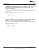
Table 8-3. Configuration of Serial Interfaces
Signal QFN48 / 7x7 QFN32 / 5x5 QFN32 / 4x4
UART0 RX UART_RX DIO2 DIO1 DIO1
UART0 TX UART_TX DIO3 DIO0 DIO2
SSI0 Clk SSP_CLK DIO10 DIO10 DIO8
SSI0 Fss SSP_FSS DIO11 DIO9 DIO7
SSI0 RX SSP_RX DIO9 DIO11 DIO9
SSI0 TX SSP_TX DIO8 DIO12 DIO0
The bootloader will initially configure only the input pins on the two serial interfaces. Because all I/O-pins,
by default, have their input buffers disabled, the bootloader will configure the required pins to be input pins
so that the bootloader interface will not be accessible from a host before this point in time. For this initial
configuration of input pins, the firmware will configure the IOC to route the input signals listed in Table 8-3
to their corresponding peripheral signals.
The bootloader will select the interface that is the first to be accessed by the external device. Once
selected, the TX output pin for the selected interface is configured; the module on the inactive interface
(UART0 or SSI0) is disabled. To switch to the other interface, the CC26xx devices must be reset. The
delayed configuration of the TX pin imposes special consideration on an SSI0 master device regarding the
transfer of the first byte of the first packet. See Section 8.2.2.2, SSI Transport.
8.2.2.1 UART Transport
The connections required to use the UART port are the following two pins: UART0 TX and UART0 RX.
The device communicating with the bootloader drives the UART0 RX pin on the CC26xx, while the
CC26xx drives the UART0 TX pin.
While the baud rate is flexible, the UART serial format is fixed at 8 data bits, no parity, and 1 stop bit. The
bootloader automatically detects the baud rate for communication. The only requirement on baud rate is
that the baud rate should be no more than 1/16 of the frequency of the UART module clock in CC26xx.
8.2.2.1.1 UART Baud Rate Auto-Detection
The bootloader provides a method to automatically detect the UART baud rate being used to
communicate with it.
To synchronize with the host, the bootloader must to receive 2 bytes with the value of 0x55. If
synchronization succeeds, the bootloader will return an acknowledge consisting of 2 bytes with the values
of 0x00 and 0xCC.
If synchronization fails, the bootloader waits for synchronization attempts.
In the automatic-detection function, the UART0 RX pin is monitored for edges using GPIO interrupts.
When enough edges are detected, the bootloader determines the ratio of baud rate and frequency needed
to program the UART.
The UART module system clock must be at least 16 times the baud rate; thus, the maximum baud rate
can be no higher than 3 Mbaud (48 MHz divided by 16). The maximum baud rate will be restricted to 1.6
Mbaud because of the firmware function that detects the transfer rate of the host.
8.2.2.2 SSI Transport
The connections required to use the SSI port are the following four pins:
• SSI0 TX
• SSI0 RX
• SSI0 Clk
• SSI0 Fss
The device communicating with the bootloader drives the SSI0 RX, SSI0 Clk, and SSI0 Fss pins, while the
CC26xx drives the SSI0 TX pin.
675
SWCU117A–February 2015–Revised March 2015 Bootloader
Submit Documentation Feedback
Copyright © 2015, Texas Instruments Incorporated