
User manual


0x06
0x03
0x84 0x48
0x6f
0x6c 0x61 0x00
0x00 0xcc
ACK
size checksum data
Bootloader Interfaces
www.ti.com
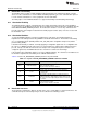
To illustrate packet handling, the basic packet format is shown in Figure 8-1.
In Figure 8-1, the top line shows the device that is transmitting data; the bottom line is the response from
the other device.
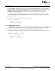
In this case, a 6-byte packet is sent with the data shown in Figure 8-2. This data results in a checksum of
0x48+0x6f+0x6c+0x61 which, when truncated to 8 bits, is 0x84. The first byte transmitted holds the size of
the packet in number of bytes. Then the checksum byte is transmitted. The next bytes to go out are the 4
data bytes in this packet. The transmitter is allowed to send zeros until a nonzero response is received,
that is necessary for SSI and is allowed by the UART. The receiver is allowed to return zeros until it is
ready to ACK or NAK the packet that is being sent. Neither device should transfer a nonzero byte until it
has received a response after transmitting a packet.
Figure 8-2. Serial Bus Packet Format
8.2.1.1 Packet Acknowledge and Not-Acknowledge Bytes
Table 8-2 shows the defined values for packet acknowledge (ACK) and not-acknowledge (NAK) bytes.
Table 8-2. Protocol Acknowledge/Not-Acknowledge
Bytes
Protocol Byte Value
ACK 0×CC
NACK 0×33
8.2.2 Transport Layer
The bootloader supports updating through the UART0 and SSI0 ports, which are available on the CC26xx
devices. The SSI0 port has the advantage of supporting higher and more flexible data rates, but it also
requires more connections to the CC26xx device. The UART0 has the disadvantage of having slightly
lower and possibly less flexible rates. However, the UART0 requires fewer pins and can be easily
implemented with any standard UART connection.
Table 8-3 specifies which serial interface signals will be configured to specific DIOs. These pins are fixed
and cannot be reconfigured.
674
Bootloader SWCU117A–February 2015–Revised March 2015
Submit Documentation Feedback
Copyright © 2015, Texas Instruments Incorporated