
User manual


www.ti.com
PRCM Registers
6.2.1.32 I2SCLKCTL Register (Offset = D0h) [reset = X]
I2SCLKCTL is shown in Figure 6-38 and described in Table 6-40.
I2S Clock Control
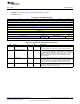
Figure 6-38. I2SCLKCTL Register
31 30 29 28 27 26 25 24
RESERVED
R-X
23 22 21 20 19 18 17 16
RESERVED
R-X
15 14 13 12 11 10 9 8
RESERVED
R-X
7 6 5 4 3 2 1 0
RESERVED SMPL_ON_PO WCLK_PHASE EN
SEDGE
R-X R/W-X R/W-X R/W-X
Table 6-40. I2SCLKCTL Register Field Descriptions
Bit Field Type Reset Description
31-4 RESERVED R X
Software should not rely on the value of a reserved. Writing any
other value than the reset value may result in undefined behavior.
3 SMPL_ON_POSEDGE R/W X
On the I2S serial interface, data and WCLK is sampled and clocked
out on opposite edges of BCLK. 0 - data and WCLK are sampled on
the negative edge and clocked out on the positive edge. 1 - data and
WCLK are sampled on the positive edge and clocked out on the
negative edge. For changes to take effect, CLKLOADCTL.LOAD
needs to be written
2-1 WCLK_PHASE R/W X
Decides how the WCLK division ratio is calculated and used to
generate different duty cycles (See I2SWCLKDIV.WDIV). 0: Single
phase 1: Dual phase 2: User Defined 3: Reserved/Undefined For
changes to take effect, CLKLOADCTL.LOAD needs to be written
0 EN R/W X
0: MCLK, BCLK and **WCLK** will be static low 1: Enables the
generation of MCLK, BCLK and WCLK For changes to take effect,
CLKLOADCTL.LOAD needs to be written
461
SWCU117A–February 2015–Revised March 2015 Power, Reset, and Clock Management
Submit Documentation Feedback
Copyright © 2015, Texas Instruments Incorporated