
User manual


www.ti.com
Introduction
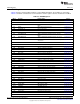
Table 6-5. Power Modes as Defined in TI-RTOS
Mode Software Configurable Power Modes Reset Pin Held
Active Idle Standby Shutdown
System CPU Active Off Off Off Off
System SRAM On On Retained Off Off
Register retention
(1)
Full Full Partial No No
VIMS_PD (flash) On Available Off Off Off
RFCORE_PD (radio) Available Available Off Off Off
SERIAL_PD Available Available Off Off Off
PERIPH_PD Available Available Off Off Off
Sensor controller Available Available Available Off Off
Supply system On On Duty-cycled Off Off
Current Application Application ≈1 µA ≈0.1 µA ≈0.1 µA
dependent dependent
Time from CPU – TBD TBD TBD –
active to ready for
Wakeup
(2)
Wakeup time to CPU – 25 µs 300 µs
(3)
≈1.5 ms ≈1.5 ms
active
(2)
High-speed clock XOSC_HF or XOSC_HF or Off Off Off
RCOSC_HF RCOSC_HF
Low-speed clock XOSC_LF or XOSC_LF or XOSC_LF or Off Off
RCOSC_LF RCOSC_LF RCOSC_LF
Wakeup on RTC Available Available Available Off Off
Wakeup on pin edge Available Available Available Available Off
Wakeup on reset pin Available Available Available Available Available
(1)
See Figure 6-3 for modules with retention.
(2)
Numbers include TI-RTOS overhead
(3)
Note that when an emulator/debugger is attached to the device the wakeup time is approximately 200 us shorter as the system will not
enter true standby.
6.1.5.1 Startup State
The CC26xx state after a system reset, power on, or wakeup from shutdown is as follows:
• Global LDO active
• Digital LDO active
• AON_VD powered
– AUX_PD powered
– JTAG_PD powered off
• MCU_VD powered
– MCU_AON powered
– CPU_PD powered
• System CPU in run mode
– BUS_PD powered
• SYSBUS clock running
– VIMS_PD powered
• VIMS clock running
– All other power domains off
– All digital module clocks disabled
423
SWCU117A–February 2015–Revised March 2015 Power, Reset, and Clock Management
Submit Documentation Feedback
Copyright © 2015, Texas Instruments Incorporated