
User manual


ICEPick™
www.ti.com
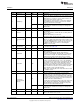
Table 5-21. Secondary Debug TAP Register [SDTR]
Bit Field Width Type Reset Description
23-21 Reserved 3 RW 0 Reserved
When 0, this bit does not influence the clock and the power
settings to the module.
While this bit is 1, if power or clock for TAP’s module is not
W 0 allowed to be turned off once turned on.
If the target does not have power or clock when setting this
20 InhibitSleep 1
bit, InhibitSleep will not change power/clock state until the
target is powered and clocked again.
The value read does not reflect the value written until the
R - power and clock controller has acted upon a change in the
written value.
19:18 Reserved 2 R ‑ Reserved
The InReset status and the ReleaseFromWIR control share
the same bit.
17 InReset 1 R ‑ When 1, the module(s) controlled by the secondary TAP is in
the reset state.
When 0, the module(s) is not in reset.
The InReset status and the ReleaseFromWIR control share
the same bit.
When a 1 is written to this bit and the module is held in reset
ReleaseFromWI
W 0 due to the WaitInReset bit, the module reset is released. This
R
only occurs if WaitInReset is 1 and it is the only cause for
holding the module in reset. This is a self‑clearing bit.
Writing a 0 has no effect.
Override the application controls of the functional warm reset
16-14 ResetControl 3 RW 0
to a module. See Table 5-22
13-10 Reserved 4 RW 0 Reserved
When 1, the TAP is currently selected and visible in the
active scan chain.
The VisibleTap bit indicates that the TAP, which was
9 VisibleTAP 1 R -
previously selected with the SelectTap bit, is now part of the
device master scan path. The VisibleTap bit will be set by
ICEPick once the Run‑Test‑Idle state has been reached.
The SelectTap bit allows scan controller software to change
which secondary TAPs are included in the device level
master scan path. When this bit is set to 1, the TAP will be
selected for inclusion in the master scan path when the TAP
state advances to the Run‑Test‑Idle state. When this bit is
8 SelectTAP 1 RW 0 changed to 0, the TAP will be deselected from the master
scan path when the TAP state advances to the Run‑Test‑Idle
state. Selection or deselection occurs in the Run‑Test‑Idle
state regardless of the current IR instruction.
Writes to the SelectTap bit are blocked, and the bit is held at
0, if TapPresent is 0.
4-Jul Reserved 4 RW 0 Reserved
When ForceActive is 0, the module ’s clock and power
settings follow the normal application settings unless one of
the other emulation controls is affecting the state. Setting the
ForceActive bit will cause the power and clock held on and to
be turned on if necessary. In this sense, the ForceActive bit
W -
could be named ForcePowerAndClock.
ForceActive
Clearing the ForceActive bit returns control of the power and
3 (ForcePowerAn 1
clock settings to the application. If the application controls
dClock)
indicate that the power and clock should be off, the power
and clock to the module will be turned off.
The value read does not reflect the value written until the
R - power and clock controller has acted upon a change in the
written value.
2 Reserved 1 R - Reserved
When 0, the TAP cannot be accessed due to security.
1 TapAccessible 1 R -
When 1, the TAP can be accessed.
406
JTAG Interface SWCU117A–February 2015–Revised March 2015
Submit Documentation Feedback
Copyright © 2015, Texas Instruments Incorporated