
User manual


www.ti.com
ICEPick™
5.3.2 ICEPick™ Registers
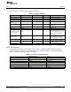
Table 5-6 lists the control and status registers in ICEPick.
Table 5-6. Register Summary
Register Abbreviation Width Number Description
Data Shift Register DSR 32 1 TAP Data Register
Instruction Register IR 6 1 TAP Instruction Register
Bypass Register Bypass 1 1 Used by the BYPASS instruction
Device Identification
TAPID 32 1 Device ID used with IDCODE
Register
User Code used with
User Code Register UC 32 1
USERCODE
ICEPick Identification IPID 32 1 Version of ICEPick
Connect Connect 7 1 Connect code
One register exists for each
debug TAP instantiated. It is used
Secondary Debug TAP
SDTR 24 1 to control selection, power, reset,
Register (SDTR)
and the clock associated with
each TAP.
One register exists for each test
Secondary Test TAP
STTR 24 6 TAP instantiated. It is used to
Register (STTR)
control selection of each TAP.
Reserved SUTR 24 1 Reserved
Specifies how ICEPick manages
Linking Mode LMR 24 1
the TAP selection.
ICEPick Control IPCR 24 1 General ICEPick control
5.3.2.1 IR Instructions
The ICEPick TAP supports the instructions listed in Table 5-7. All unused TAP controller instructions
default to the bypass register. Several instructions are reserved for extensions to the ICEPick opcodes.
Refer to for device identification register descriptions.
Table 5-7. Instruction Register Opcodes
IR ICEPick Instruction Access
000000, 111111 BYPASS Always-open
10 ROUTER Connected
100 IDCODE Always-open
101 ICEPICKCODE Always-open
111 CONNECT Always-open
1000 USERCODE Always-open
000001, 000011, 000110, 001001–111110 Reserved Reserved
399
SWCU117A–February 2015–Revised March 2015 JTAG Interface
Submit Documentation Feedback
Copyright © 2015, Texas Instruments Incorporated