
User manual


www.ti.com
AON Event Fabric
4.4.1 Common Input Event List
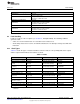
Table 4-7 lists the input events for the AON event fabric. The sources for these events are considered
level-triggered active high.
Table 4-7. AON Event Fabric Input Events
Event No. Event Enum Source Description
0x0 to 0x1F PAD0 to PAD31 Edge detector Edge detect on specific I/O
0x20 PAD Edge detector Edge detect on any I/O
0x21 SPIS_BYTE_DONE SPIS SPIS AON_SPISLAVE byte received or transmitted
0x22 SPIS_CS SPIS SPIS AON_SPISLAVE chip select pin asserted
0x23 to 0x25 RTC_CH0 to RTC_CH2 RTC RTC RTC channel 0 to 2 event
0x26 to 0x28 RTC_CH0_DLY toRTC_CH2_DLY RTC RTC RTC channel 0 to 2 , delayed event
0x29 RTC_COMB_DLY RTC RTC RTC combined delayed event
0x2A RTC_UPD RTC RTC RTC update tick
0x2B JTAG JTAG JTAG JTAG generated event
AUX software triggered events triggered by
0x2C to 0x2E AUX_SWEV0 to AUX_SWEV2 AUX AUX
AUX_EVCTL:SWEVSET:SWEVn
0x2F AUX_COMPA AUX comparator Comparator A triggered
0x30 AUX_COMPB AUX comparator Comparator B triggered
0x31 AUX_ADC_DONE AUX ADC ADC conversion completed
0x32 AUX_TDC_DONE AUX TDC TDC completed or timed out
AUX_TIMER0_EV to
0x33 to 0x34 AUX timer Timer 0 to 1 event
AUX_TIMER1_EV
0x35 BATMON_TEMP BATMON BATMON temperature update event
0x36 BATMON_VOLT BATMON BATMON voltage update event
0x37 AUX_COMPB_ASYNC AUX comparator directly from the AUX comparator B
Comparator B not triggered. Asynchronous signal
0x38 AUX_COMPB_ASYNC_N AUX comparator
directly from AUX comparator B (inverted)
0x3F NONE Edge detector No event, always low
4.4.2 Event Subscribers
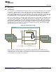
There are three subscribers in the AON event fabric as can be seen in Figure 4-5. The first subscriber is
the MCU event fabric, which resides in the MCU power domain. The other two subscribers, the WUC and
RTC, both reside in the AON power domain and are presented in the following subsections.
4.4.2.1 Wake-up Controller (WUC)
The WUC receives output signals from the WUC subscriber in the AON event fabric where power-on
sequences can be triggered by configured input events from JTAG, AUX, or the MCU. JTAG has one
wake-up event going to the WUC, while the AUX domain has three programmable input events and the
MCU domain has four programmable input events. These specific input events are ORed together to form
a single input to the WUC, one from the MCU and one from the AUX. Figure 4-5 shows this configuration.
The inputs can be configured in the two selection registers, [CTRL_AUX_WU]/[CTRL _WU_AUX] and
[CTRL_MCU_WU]/[CTRL _WU_MCU]. Any of the events listed in Table 4-7 can be chosen as input by
choosing the appropriate event ID. By default, these IDs are set to 63 (NULL, no event), where the lines
always stay logic low.
239
SWCU117A–February 2015–Revised March 2015 Interrupts and Events
Submit Documentation Feedback
Copyright © 2015, Texas Instruments Incorporated