
User manual


www.ti.com
Cortex-M3 Processor Registers
2.7.5.4 SPPR Register (Offset = F0h) [reset = X]
SPPR is shown in Figure 2-134 and described in Table 2-161.
Selected Pin Protocol This register selects the protocol to be used for trace output. Note: If this register is
changed while trace data is being output, data corruption occurs.
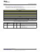
Figure 2-134. SPPR Register
31 30 29 28 27 26 25 24
RESERVED
R/W-X
23 22 21 20 19 18 17 16
RESERVED
R/W-X
15 14 13 12 11 10 9 8
RESERVED
R/W-X
7 6 5 4 3 2 1 0
RESERVED PROTOCOL
R/W-X R/W-1h
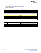
Table 2-161. SPPR Register Field Descriptions
Bit Field Type Reset Description
31-2 RESERVED R/W X
Software should not rely on the value of a reserved. Writing any
other value than the reset value may result in undefined behavior.
1-0 PROTOCOL R/W 1h
Trace output protocol
0h = TracePort mode
1h = SerialWire Output (Manchester). This is the reset value.
2h = SerialWire Output (NRZ)
211
SWCU117A–February 2015–Revised March 2015
Submit Documentation Feedback
Copyright © 2015, Texas Instruments Incorporated