
User manual


Cortex-M3 Processor Registers
www.ti.com
2.7.4.58 DCRDR Register (Offset = DF8h) [reset = 0h]
DCRDR is shown in Figure 2-128 and described in Table 2-154.
Debug Core Register Data
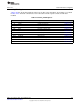
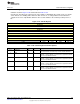
Figure 2-128. DCRDR Register
31 30 29 28 27 26 25 24 23 22 21 20 19 18 17 16 15 14 13 12 11 10 9 8 7 6 5 4 3 2 1 0
DCRDR
R/W-0h
Table 2-154. DCRDR Register Field Descriptions
Bit Field Type Reset Description
31-0 DCRDR R/W 0h
This register holds data for reading and writing registers to and from
the processor. This is the data value written to the register selected
by DCRSR. When the processor receives a request from DCRSR,
this register is read or written by the processor using a normal load-
store unit operation. If core register transfers are not being
performed, software-based debug monitors can use this register for
communication in non-halting debug. This enables flags and bits to
acknowledge state and indicate if commands have been accepted
to, replied to, or accepted and replied to.
202
SWCU117A–February 2015–Revised March 2015
Submit Documentation Feedback
Copyright © 2015, Texas Instruments Incorporated