
User manual


www.ti.com
Cortex-M3 Processor Registers
2.7.4.56 DHCSR Register (Offset = DF0h) [reset = X]
DHCSR is shown in Figure 2-126 and described in Table 2-152.
Debug Halting Control and Status The purpose of this register is to provide status information about the
state of the processor, enable core debug, halt and step the processor. For writes, 0xA05F must be
written to higher half-word of this register, otherwise the write operation is ignored and no bits are written
into the register. If not enabled for Halting mode, C_DEBUGEN = 1, all other fields are disabled. This
register is not reset on a core reset. It is reset by a power-on reset. However, C_HALT always clears on a
core reset. To halt on a reset, the following bits must be enabled: DEMCR.VC_CORERESET and
C_DEBUGEN. Note that writes to this register in any size other than word are unpredictable. It is
acceptable to read in any size, and it can be used to avoid or intentionally change a sticky bit. Behavior of
the system when writing to this register while CPU is halted (i.e. C_DEBUGEN = 1 and S_HALT= 1):
C_HALT=0, C_STEP=0, C_MASKINTS=0 Exit Debug state and start instruction execution. Exceptions
activate according to the exception configuration rules. C_HALT=0, C_STEP=0, C_MASKINTS=1 Exit
Debug state and start instruction execution. PendSV, SysTick and external configurable interrupts are
disabled, otherwise exceptions activate according to standard configuration rules. C_HALT=0, C_STEP=1,
C_MASKINTS=0 Exit Debug state, step an instruction and halt. Exceptions activate according to the
exception configuration rules. C_HALT=0, C_STEP=1, C_MASKINTS=1 Exit Debug state, step an
instruction and halt. PendSV, SysTick and external configurable interrupts are disabled, otherwise
exceptions activate according to standard configuration rules. C_HALT=1, C_STEP=x, C_MASKINTS=x
Remain in Debug state
Figure 2-126. DHCSR Register
31 30 29 28 27 26 25 24
RESERVED S_RESET_ST S_RETIRE_ST
R/W-X R/W-X R/W-X
23 22 21 20 19 18 17 16
RESERVED S_LOCKUP S_SLEEP S_HALT S_REGRDY
R/W-X R/W-X R/W-X R/W-X R/W-0h
15 14 13 12 11 10 9 8
RESERVED
R-X
7 6 5 4 3 2 1 0
RESERVED C_SNAPSTALL RESERVED C_MASKINTS C_STEP C_HALT C_DEBUGEN
R-X R/W-X R/W-X R/W-X R/W-X R/W-X R/W-X
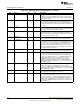
Table 2-152. DHCSR Register Field Descriptions
Bit Field Type Reset Description
31-26 RESERVED R/W X
Software should not rely on the value of a reserved. When writing to
this register, 0x28 must be written this bit-field, otherwise the write
operation is ignored and no bits are written into the register.
25 S_RESET_ST R/W X
Indicates that the core has been reset, or is now being reset, since
the last time this bit was read. This a sticky bit that clears on read.
So, reading twice and getting 1 then 0 means it was reset in the
past. Reading twice and getting 1 both times means that it is being
reset now (held in reset still). When writing to this register, 0 must be
written this bit-field, otherwise the write operation is ignored and no
bits are written into the register.
24 S_RETIRE_ST R/W X
Indicates that an instruction has completed since last read. This is a
sticky bit that clears on read. This determines if the core is stalled on
a load/store or fetch. When writing to this register, 0 must be written
this bit-field, otherwise the write operation is ignored and no bits are
written into the register.
23-20 RESERVED R/W X
Software should not rely on the value of a reserved. When writing to
this register, 0x5 must be written this bit-field, otherwise the write
operation is ignored and no bits are written into the register.
199
SWCU117A–February 2015–Revised March 2015
Submit Documentation Feedback
Copyright © 2015, Texas Instruments Incorporated