
User manual


Command ID (16 bits)
31
msb
24 16 8
0
lsb
2
0
1
Optional parameter
Optional par.
extension
Pointer to command structure (bits 31:2)
31
msb
24 16 8
0
lsb
2
0 0
RF Core HAL
www.ti.com
23.3.2.1 Commands
The radio CPU lets the user run a set of high-level primitives or commands from the system CPU. After a
command has been issued through the [CMDR] register, the radio CPU examines it and decides a course
of action.
There are three classes of commands issued:
• Radio operation command
• Immediate command
• Direct command
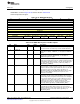
For the first two classes of commands, [CMDR] contains a pointer to a command structure in the radio
RAM. This must be a valid pointer with 32-bit word alignment, so the two least significant bits must be
zero, as shown in Figure 23-3. A direct command is signaled by setting the two least significant bits to 01
and placing the command ID number in bits 16 to 31 of [CMDR]. Bits 8 through 15, or alternatively 2
through 15, may be used as an optional byte parameter. The format for a direct command is shown in
Figure 23-4.
Figure 23-3. CMDR Register for Radio Operation Commands and Immediate Commands
Figure 23-4. CMDR Register for Direct Commands
The data structure pointed to by the [CMDR] register for radio operation and immediate commands may
be in the system RAM, the radio RAM, or flash (the latter is only possible if the radio CPU will not write
anything to the command structure). The system CPU must ensure that the memory area in use is free for
access, in particular when using the radio RAM, where a part of the memory will be reserved for use by
the radio CPU. This information may be obtained with the CMD_GET_FW_INFO command (see
Section 23.3.4.6). The format of the command follows a structure as given in Section 23.3.2.6, Command
Data Structures, with subsections, and will be defined in more detail specifically for each command.
When deciding in which memory area to place data, take into account what modules may be powered
down:
• The radio RAM is accessible for the radio CPU at any time, but does not have retention when the radio
is powered down. Data that must be retained must therefore be copied in and out of the radio RAM
whenever the radio is powered up or down, respectively.
• The system RAM has retention in most low-power modes. If the system side is powered down, the
radio CPU will request it to be powered up again to access the RAM. The active current consumption
from the radio CPU accessing the system RAM is higher than from accessing the radio RAM,
especially if the system side could otherwise have been powered down.
• The flash always has retention, and can only store parameters that will not be written by the radio
CPU. As with accessing the system RAM, the radio CPU has to ensure that the system side is
powered up to access the flash. The power consumption from the radio CPU accessing the flash will
be higher than from accessing the system RAM, but in most cases the difference will be negligible due
to few accesses.
• The lowest peak-power consumption is obtained by putting all data structures in the radio RAM and
powering down the system side while the radio CPU is running. In some cases the average power
consumption may be lower by putting data structures in the system RAM, as less copying is then
needed, and the system side can still be powered down for long periods, for instance while the receiver
is in sync search.
1458
Radio SWCU117A–February 2015–Revised March 2015
Submit Documentation Feedback
Copyright © 2015, Texas Instruments Incorporated