
User manual


I2S Registers
www.ti.com
22.10.1.27 IRQMASK Register (Offset = 70h) [reset = X]
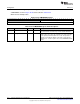
IRQMASK is shown in Figure 22-34 and described in Table 22-28.
Masked Interrupt Status Register
Figure 22-34. IRQMASK Register
31 30 29 28 27 26 25 24
RESERVED
R/W-X
23 22 21 20 19 18 17 16
RESERVED
R/W-X
15 14 13 12 11 10 9 8
RESERVED
R/W-X
7 6 5 4 3 2 1 0
RESERVED AIF_DMA_IN AIF_DMA_OUT WCLK_TIMEO BUS_ERR WCLK_ERR PTR_ERR
UT
R/W-X R/W-X R/W-X R/W-X R/W-X R/W-X R/W-X
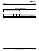
Table 22-28. IRQMASK Register Field Descriptions
Bit Field Type Reset Description
31-6 RESERVED R/W X
Software should not rely on the value of a reserved. Writing any
other value than the reset value may result in undefined behavior.
5 AIF_DMA_IN R/W X
Defines the masks state for the interrupt of IRQFLAGS.AIF_DMA_IN
0: Disable 1: Enable
4 AIF_DMA_OUT R/W X
Defines the masks state for the interrupt of
IRQFLAGS.AIF_DMA_OUT 0: Disable 1: Enable
3 WCLK_TIMEOUT R/W X
Defines the masks state for the interrupt of
IRQFLAGS.WCLK_TIMEOUT 0: Disable 1: Enable
2 BUS_ERR R/W X
Defines the masks state for the interrupt of IRQFLAGS.BUS_ERR 0:
Disable 1: Enable
1 WCLK_ERR R/W X
Defines the masks state for the interrupt of IRQFLAGS.WCLK_ERR
0: Disable 1: Enable
0 PTR_ERR R/W X
Defines the masks state for the interrupt of IRQFLAGS.PTR_ERR 0:
Disable 1: Enable
1450
Integrated Interchip Sound (I2S) Module SWCU117A–February 2015–Revised March 2015
Submit Documentation Feedback
Copyright © 2015, Texas Instruments Incorporated