
User manual


I2S Registers
www.ti.com
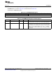
22.10.1.13 STMPCTL Register (Offset = 34h) [reset = X]
STMPCTL is shown in Figure 22-20 and described in Table 22-14.
SampleStaMP Generator Control Register
Figure 22-20. STMPCTL Register
31 30 29 28 27 26 25 24
RESERVED
R-X
23 22 21 20 19 18 17 16
RESERVED
R-X
15 14 13 12 11 10 9 8
RESERVED
R-X
7 6 5 4 3 2 1 0
RESERVED OUT_RDY IN_RDY STMP_EN
R-X R-X R-X R/W-X
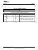
Table 22-14. STMPCTL Register Field Descriptions
Bit Field Type Reset Description
31-3 RESERVED R X
Software should not rely on the value of a reserved. Writing any
other value than the reset value may result in undefined behavior.
2 OUT_RDY R X
Low until the output pins are ready to be started by the samplestamp
generator. When started (i.e. STMPOUTTRIG equals the WCLK
counter) the bit goes back low.
1 IN_RDY R X
Low until the input pins are ready to be started by the samplestamp
generator. When started (i.e. STMPINTRIG equals the WCLK
counter) the bit goes back low.
0 STMP_EN R/W X
Enables the samplestamp generator. The samplestamp generator
should only be enabled after it has been properly configured. When
cleared, all samplestamp generator counters and capture values are
cleared.
1436
Integrated Interchip Sound (I2S) Module SWCU117A–February 2015–Revised March 2015
Submit Documentation Feedback
Copyright © 2015, Texas Instruments Incorporated