
User manual


I2S Registers
www.ti.com
22.10.1.3 AIFDIRCFG Register (Offset = 8h) [reset = X]
AIFDIRCFG is shown in Figure 22-10 and described in Table 22-4.
Pin Direction
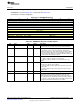
Figure 22-10. AIFDIRCFG Register
31 30 29 28 27 26 25 24
RESERVED
R-X
23 22 21 20 19 18 17 16
RESERVED
R-X
15 14 13 12 11 10 9 8
RESERVED AD2
R-X R/W-X
7 6 5 4 3 2 1 0
RESERVED AD1 RESERVED AD0
R-X R/W-X R-X R/W-X
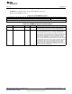
Table 22-4. AIFDIRCFG Register Field Descriptions
Bit Field Type Reset Description
31-10 RESERVED R X
Software should not rely on the value of a reserved. Writing any
other value than the reset value may result in undefined behavior.
9-8 AD2 R/W X
Configures the AD2 audio data pin usage 0x3: Reserved
0h = Not in use (disabled)
1h = Input mode
2h = Output mode
7-6 RESERVED R X
Software should not rely on the value of a reserved. Writing any
other value than the reset value may result in undefined behavior.
5-4 AD1 R/W X
Configures the AD1 audio data pin usage: 0x3: Reserved
0h = Not in use (disabled)
1h = Input mode
2h = Output mode
3-2 RESERVED R X
Software should not rely on the value of a reserved. Writing any
other value than the reset value may result in undefined behavior.
1-0 AD0 R/W X
Configures the AD0 audio data pin usage: 0x3: Reserved
0h = Not in use (disabled)
1h = Input mode
2h = Output mode
1426
Integrated Interchip Sound (I2S) Module SWCU117A–February 2015–Revised March 2015
Submit Documentation Feedback
Copyright © 2015, Texas Instruments Incorporated