
User manual


[I2S:STMPXCNTCAPT0]
[I2S:STMPWPER]
STMPWCNT
STMPXCNT
samplestamp_req
WCLK_pos_edge
samplestamp_req
[I2S:STMPINTRIG]
[I2S:STMPOUTTRIG]
=
=
1
[I2S:STMPXCNTCAPT1]
[I2S:STMPXPER]
[I2S:STMPXCNTCAPT0]
[I2S:STMPXCNTCAPT1]
[I2S:STMPCTL:IN_RDY]
[I2S:STMPCTL:OUT_RDY]
WCLK_pos_edge
www.ti.com
Samplestamp Generator
22.8.1 Counters and Registers
The samplestamp generator contains two different parts that are based on two counters:
1. STMPXCNT counts XOSC (clock) cycles between positive WCLK edges. The counter value can be
read from the [I2S:STMPXCNT] register.
2. STMPWCNT counts positive WCLK edges and modulo the size of the sample ring-buffer. The modulo
value is given by the [I2S:STMPWPER] register. The counter value can be read from the
[I2S:STMPWCNT] register.
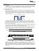
The lower part of Figure 22-7 shows the part of the samplestamp generator that is used by the I2S module
to control the I/O pins on the serial audio interface.
The upper part of Figure 22-7, inside the dotted line, includes optional functionality in the form of capturing
registers which can be used, for example, in real-time streaming applications to achieve fixed latency and
I2S synchronization in a wireless network.
Figure 22-7. Samplestamp Generator Structure
NOTE: During start-up, if WCLK is high during the first BCLK cycles, there can be one or two false
WCLK_pos_edge pulses:
• One due to the level of the selected WCLK source
• Another if the [I2S:AIFFMTCFG:SMPL_EDGE] register is not changed from 1 to 0
before BCLK starts running
1419
SWCU117A–February 2015–Revised March 2015 Integrated Interchip Sound (I2S) Module
Submit Documentation Feedback
Copyright © 2015, Texas Instruments Incorporated