
User manual


www.ti.com
SSI Registers
20.7.1.2 CR1 Register (Offset = 4h) [reset = X]
CR1 is shown in Figure 20-14 and described in Table 20-4.
Control 1
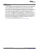
Figure 20-14. CR1 Register
31 30 29 28 27 26 25 24 23 22 21 20 19 18 17 16
RESERVED
R-X
15 14 13 12 11 10 9 8 7 6 5 4 3 2 1 0
RESERVED SOD MS SSE LBM
R-X R/W-X R/W-X R/W-X R/W-X
Table 20-4. CR1 Register Field Descriptions
Bit Field Type Reset Description
31-4 RESERVED R X
Software should not rely on the value of a reserved. Writing any
other value than the reset value may result in undefined behavior.
3 SOD R/W X
Slave-mode output disabled This bit is relevant only in the slave
mode, MS=1. In multiple-slave systems, it is possible for an SSI
master to broadcast a message to all slaves in the system while
ensuring that only one slave drives data onto its serial output line. In
such systems the RXD lines from multiple slaves could be tied
together. To operate in such systems, this bitfield can be set if the
SSI slave is not supposed to drive the TXD line: 0: SSI can drive the
TXD output in slave mode. 1: SSI cannot drive the TXD output in
slave mode.
2 MS R/W X
Master or slave mode select. This bit can be modified only when SSI
is disabled, SSE=0.
0h = Device configured as master
1h = Device configured as slave
1 SSE R/W X
Synchronous serial interface enable.
0h = SSI_DISABLED : Operation disabled
1h = SSI_ENABLED : Operation enabled
0 LBM R/W X
Loop back mode: 0: Normal serial port operation enabled. 1: Output
of transmit serial shifter is connected to input of receive serial shifter
internally.
1369
SWCU117A–February 2015–Revised March 2015 Synchronous Serial Interface (SSI)
Submit Documentation Feedback
Copyright © 2015, Texas Instruments Incorporated