
User manual


www.ti.com
UARTS Registers
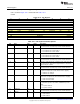
19.7.1.7 LCRH Register (Offset = 2Ch) [reset = X]
LCRH is shown in Figure 19-10 and described in Table 19-10.
Line Control
Figure 19-10. LCRH Register
31 30 29 28 27 26 25 24
RESERVED
R/W-X
23 22 21 20 19 18 17 16
RESERVED
R/W-X
15 14 13 12 11 10 9 8
RESERVED
R/W-X
7 6 5 4 3 2 1 0
SPS WLEN FEN STP2 EPS PEN BRK
R/W-X R/W-X R/W-X R/W-X R/W-X R/W-X R/W-X
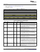
Table 19-10. LCRH Register Field Descriptions
Bit Field Type Reset Description
31-8 RESERVED R/W X
Software should not rely on the value of a reserved. Writing any
other value than the reset value may result in undefined behavior.
7 SPS R/W X
UART Stick Parity Select: 0: Stick parity is disabled 1: The parity bit
is transmitted and checked as invert of EPS field (i.e. the parity bit is
transmitted and checked as 1 when EPS = 0). This bit has no effect
when PEN disables parity checking and generation.
6-5 WLEN R/W X
UART Word Length: These bits indicate the number of data bits
transmitted or received in a frame.
0h = 5 : Word Length 5 bits
1h = 6 : Word Length 6 bits
2h = 7 : Word Length 7 bits
3h = 8 : Word Length 8 bits
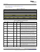
4 FEN R/W X
UART Enable FIFOs
0h = FIFOs are disabled (character mode) that is, the FIFOs become
1-byte-deep holding registers.
1h = Transmit and receive FIFO buffers are enabled (FIFO mode)
3 STP2 R/W X
UART Two Stop Bits Select: If this bit is set to 1, two stop bits are
transmitted at the end of the frame. The receive logic does not check
for two stop bits being received.
2 EPS R/W X
UART Even Parity Select
0h = Odd parity: The UART generates or checks for an odd number
of 1s in the data and parity bits.
1h = Even parity: The UART generates or checks for an even
number of 1s in the data and parity bits.
1 PEN R/W X
UART Parity Enable This bit controls generation and checking of
parity bit.
0h = Parity is disabled and no parity bit is added to the data frame
1h = Parity checking and generation is enabled.
0 BRK R/W X
UART Send Break If this bit is set to 1, a low-level is continually
output on the UARTTXD output pin, after completing transmission of
the current character. For the proper execution of the break
command, the software must set this bit for at least two complete
frames. For normal use, this bit must be cleared to 0.
1343
SWCU117A–February 2015–Revised March 2015 Universal Asynchronous Receivers and Transmitters (UARTS)
Submit Documentation Feedback
Copyright © 2015, Texas Instruments Incorporated