
User manual


www.ti.com
UARTS Registers
19.7.1.3 ECR Register (Offset = 4h) [reset = X]
ECR is shown in Figure 19-6 and described in Table 19-6.
Error Clear This register is mapped to the same address as RSR register. Reads from this address are
associated with RSR register and return the receive status. Writes to this address are associated with
ECR register and clear the receive status flags (framing, parity, break, and overrun errors).
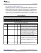
Figure 19-6. ECR Register
31 30 29 28 27 26 25 24 23 22 21 20 19 18 17 16
RESERVED
W-X
15 14 13 12 11 10 9 8 7 6 5 4 3 2 1 0
RESERVED OE BE PE FE
W-X W-X W-X W-X W-X
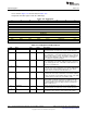
Table 19-6. ECR Register Field Descriptions
Bit Field Type Reset Description
31-4 RESERVED W X
Software should not rely on the value of a reserved. Writing any
other value than the reset value may result in undefined behavior.
3 OE W X
The framing (FE), parity (PE), break (BE) and overrun (OE) errors
are cleared to 0 by any write to this register.
2 BE W X
The framing (FE), parity (PE), break (BE) and overrun (OE) errors
are cleared to 0 by any write to this register.
1 PE W X
The framing (FE), parity (PE), break (BE) and overrun (OE) errors
are cleared to 0 by any write to this register.
0 FE W X
The framing (FE), parity (PE), break (BE) and overrun (OE) errors
are cleared to 0 by any write to this register.
1339
SWCU117A–February 2015–Revised March 2015 Universal Asynchronous Receivers and Transmitters (UARTS)
Submit Documentation Feedback
Copyright © 2015, Texas Instruments Incorporated