
User manual


www.ti.com
AUX – Sensor Controller Registers
17.8.4.2 AUXCLK Register (Offset = 4h) [reset = X]
AUXCLK is shown in Figure 17-37 and described in Table 17-58.
AUX Clock Management This register contains bitfields that are relevant for setting up the clock to the
AUX domain.
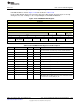
Figure 17-37. AUXCLK Register
31 30 29 28 27 26 25 24
RESERVED
R-X
23 22 21 20 19 18 17 16
RESERVED
R-X
15 14 13 12 11 10 9 8
RESERVED PWR_DWN_SRC SCLK_HF_DIV
R-X R/W-X R/W-X
7 6 5 4 3 2 1 0
RESERVED SRC
R-X R/W-1h
Table 17-58. AUXCLK Register Field Descriptions
Bit Field Type Reset Description
31-13 RESERVED R X
Software should not rely on the value of a reserved. Writing any
other value than the reset value may result in undefined behavior.
12-11 PWR_DWN_SRC R/W X
When AUX requests powerdown with SCLK_HF as source, then
WUC will switch over to this clock source during powerdown, and
automatically switch back to SCLK_HF when AUX system is back in
active mode
0h = No clock in Powerdown
1h = Use SCLK_LF in Powerdown
2h = 2
10-8 SCLK_HF_DIV R/W X
Select the AUX clock divider for SCLK_HF NB: It is not supported to
change the AUX clock divider while SCLK_HF is active source for
AUX
0h = Divide by 2
1h = Divide by 4
2h = Divide by 8
3h = Divide by 16
4h = Divide by 32
5h = Divide by 64
6h = Divide by 128
7h = Divide by 256
7-3 RESERVED R X
Software should not rely on the value of a reserved. Writing any
other value than the reset value may result in undefined behavior.
2-0 SRC R/W 1h
Selects the clock source for AUX: NB: Switching the clock source is
guaranteed to be glitchless
1h = HF Clock (SCLK_HF)
2h = 2
4h = LF Clock (SCLK_LF)
1259
SWCU117A–February 2015–Revised March 2015 AUX – Sensor Controller with Digital and Analog Peripherals
Submit Documentation Feedback
Copyright © 2015, Texas Instruments Incorporated