
User manual


www.ti.com
AUX – Sensor Controller Registers
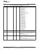
Table 17-40. VECCFG0 Register Field Descriptions (continued)
Bit Field Type Reset Description
12-8 VEC1_EV R/W X
Selects vector 1 trigger source event.
0h = AON_RTC_CH2 event
1h = AUX_COMPA event
2h = AUX_COMPB event
3h = TDC_DONE event
4h = TIMER0_EV event
5h = TIMER1_EV event
6h = SMPH_AUTOTAKE_DONE event
7h = ADC_DONE event
8h = ADC_FIFO_ALMOST_FULL event
9h = OBSMUX0 event
Ah = OBSMUX1 event
Bh = AON_SW event
Ch = AON_PROG_WU event
Dh = AUXIO0 input data
Eh = AUXIO1 input data
Fh = AUXIO2 input data
10h = AUXIO3 input data
11h = AUXIO4 input data
12h = AUXIO5 input data
13h = AUXIO6 input data
14h = AUXIO7 input data
15h = AUXIO8 input data
16h = AUXIO9 input data
17h = AUXIO10 input data
18h = AUXIO11 input data
19h = AUXIO12 input data
1Ah = AUXIO13 input data
1Bh = AUXIO14 input data
1Ch = AUXIO15 input data
1Dh = ACLK_REF event
1Eh = MCU_EV event
1Fh = ADC_IRQ event
7 RESERVED R X
Software should not rely on the value of a reserved. Writing any
other value than the reset value may result in undefined behavior.
6 VEC0_POL R/W X
Selects vector 0 trigger event polarity. To manually trigger vector 0
execution, set VEC0_EV to a known static value, and toggle
VEC0_POL twice.
0h = Rising edge triggers execution.
1h = Falling edge triggers execution.
5 VEC0_EN R/W X
Enables (1) or disables (0) triggering of vector 0 execution. When
enabled, the edge selected by VEC0_POL on the event selected by
VEC0_EV will set VECFLAGS.VEC0, which in turn triggers vector 0
execution.
0h = Event detection is disabled
1h = An event selected by VEC0_EV with polarity from VEC0_POL
triggers a jump to vector #0 when AUX_SCE is in sleep
1237
SWCU117A–February 2015–Revised March 2015 AUX – Sensor Controller with Digital and Analog Peripherals
Submit Documentation Feedback
Copyright © 2015, Texas Instruments Incorporated