
User manual


AUX – Sensor Controller Registers
www.ti.com
17.8.2.1 CTL Register (Offset = 0h) [reset = X]
CTL is shown in Figure 17-10 and described in Table 17-29.
Control
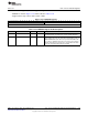
Figure 17-10. CTL Register
31 30 29 28 27 26 25 24 23 22 21 20 19 18 17 16
RESERVED
R-X
15 14 13 12 11 10 9 8 7 6 5 4 3 2 1 0
RESERVED CMD
R-X W-X
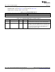
Table 17-29. CTL Register Field Descriptions
Bit Field Type Reset Description
31-2 RESERVED R X
Software should not rely on the value of a reserved. Writing any
other value than the reset value may result in undefined behavior.
1-0 CMD W X
TDC command strobes
0h = This command clears STAT.SAT, STAT.DONE and results.
Note: This is not needed as prerequisite for a measurement. Reliable
clear is only guaranteed from IDLE state
1h = This command makes the TDC FSM start counting
synchronously to the first rising edge that follows a required falling
edge of the start event. This guarantees an edge triggered start and
is recommended for frequency measurements. A falling edge of the
start event may be missed if the command is issued close to it in
time, but the TDC will catch later falling edges and guarantee that a
measurement starts synchronously to the rising edge of the start
event
2h = This command makes the TDC FSM start and stop counting
asynchronously. TDC measurement may start immediately if start is
high and hence it may not give precise edge to edge measurements.
Only recommended when start pulse is guaranteed to arrive at least
7 clock periods after the command
3h = This command forces the TDC back to IDLE state
1222
AUX – Sensor Controller with Digital and Analog Peripherals SWCU117A–February 2015–Revised March 2015
Submit Documentation Feedback
Copyright © 2015, Texas Instruments Incorporated