
User manual


AUX – Sensor Controller Registers
www.ti.com
17.8.1.2 IOMODE Register (Offset = 4h) [reset = X]
IOMODE is shown in Figure 17-4 and described in Table 17-22.
Input Output Mode Controls pull-up pull-down and output mode for the IO pins assigned to AUX
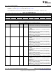
Figure 17-4. IOMODE Register
31 30 29 28 27 26 25 24 23 22 21 20 19 18 17 16
RESERVED
R-X
15 14 13 12 11 10 9 8 7 6 5 4 3 2 1 0
IO7 IO6 IO5 IO4 IO3 IO2 IO1 IO0
R/W-X R/W-X R/W-X R/W-X R/W-X R/W-X R/W-X R/W-X
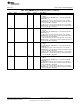
Table 17-22. IOMODE Register Field Descriptions
Bit Field Type Reset Description
31-16 RESERVED R X
Software should not rely on the value of a reserved. Writing any
other value than the reset value may result in undefined behavior.
15-14 IO7 R/W X
Selects mode for AUXIO7 (for AIODIO0) or AUXIO15 (for AIODIO1).
0h = Output
1h = Digital input with GPIODIE bit 7 = 1 Analog input/output with
GPIODIE bit 7 = 0
2h = Open-drain: The pin is driven low when the corresponding
GPIODOUT bit is 0, and otherwise tri-stated or pulled depending on
the corresponding IOC configuration.
3h = Open-source: The pin is driven high when the corresponding
GPIODOUT bit is 1, and otherwise tri-stated or pulled depending on
the corresponding IOC configuration.
13-12 IO6 R/W X
Selects mode for AUXIO6 (for AIODIO0) or AUXIO14 (for AIODIO1).
0h = Output
1h = Digital input with GPIODIE bit 6 = 1 Analog input/output with
GPIODIE bit 6 = 0
2h = Open-drain: The pin is driven low when the corresponding
GPIODOUT bit is 0, and otherwise tri-stated or pulled depending on
the corresponding IOC configuration.
3h = Open-source: The pin is driven high when the corresponding
GPIODOUT bit is 1, and otherwise tri-stated or pulled depending on
the corresponding IOC configuration.
11-10 IO5 R/W X
Selects mode for AUXIO5 (for AIODIO0) or AUXIO13 (for AIODIO1).
0h = Output
1h = Digital input with GPIODIE bit 5 = 1 Analog input/output with
GPIODIE bit 5 = 0
2h = Open-drain: The pin is driven low when the corresponding
GPIODOUT bit is 0, and otherwise tri-stated or pulled depending on
the corresponding IOC configuration.
3h = Open-source: The pin is driven high when the corresponding
GPIODOUT bit is 1, and otherwise tri-stated or pulled depending on
the corresponding IOC configuration.
9-8 IO4 R/W X
Selects mode for AUXIO4 (for AIODIO0) or AUXIO12 (for AIODIO1).
0h = Output
1h = Digital input with GPIODIE bit 4 = 1 Analog input/output with
GPIODIE bit 4 = 0
2h = Open-drain: The pin is driven low when the corresponding
GPIODOUT bit is 0, and otherwise tri-stated or pulled depending on
the corresponding IOC configuration.
3h = Open-source: The pin is driven high when the corresponding
GPIODOUT bit is 1, and otherwise tri-stated or pulled depending on
the corresponding IOC configuration.
1214
AUX – Sensor Controller with Digital and Analog Peripherals SWCU117A–February 2015–Revised March 2015
Submit Documentation Feedback
Copyright © 2015, Texas Instruments Incorporated