
User manual


AUX – Sensor Controller Registers
www.ti.com
17.8.1 AUX_AIODIO Registers
Table 17-20 lists the memory-mapped registers for the AUX_AIODIO. All register offset addresses not
listed in Table 17-20 should be considered as reserved locations and the register contents should not be
modified.
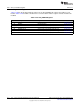
Table 17-20. AUX_AIODIO Registers
Offset Acronym Register Name Section
0h GPIODOUT General Purpose Input/Output Data Out Section 17.8.1.1
4h IOMODE Input Output Mode Section 17.8.1.2
8h GPIODIN General Purpose Input Output Data In Section 17.8.1.3
Ch GPIODOUTSET General Purpose Input Output Data Out Set Section 17.8.1.4
10h GPIODOUTCLR General Purpose Input Output Data Out Clear Section 17.8.1.5
14h GPIODOUTTGL General Purpose Input Output Data Out Toggle Section 17.8.1.6
18h GPIODIE General Purpose Input Output Input Enable Section 17.8.1.7
1212
AUX – Sensor Controller with Digital and Analog Peripherals SWCU117A–February 2015–Revised March 2015
Submit Documentation Feedback
Copyright © 2015, Texas Instruments Incorporated