
User manual


Modules
www.ti.com
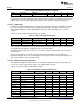
Table 17-11. Power Management Instructions
Syntax Description Operation Z N C V
wev0 #ev Wait event 0 Stop clock until events[ev] == 0 - - - -
wev1 #ev Wait event 1 Stop clock until events[ev] == 1 - - - -
sleep sleep Stop clock until wakeup, then pc - - - -
= 2*vector
When a i or wev1 instruction is executed, the sensor controller stops the clock until the selected event is
deasserted (0) or asserted (1), respectively. When the selected condition is satisfied, the clock is re-
enabled and instruction execution continues sequentially.
The wev0 and wev1 instructions use the same event inputs to the sensor controller as for the instructions
bev0 and bev1 . They are described in Section 17.4.2.1.2, Sensor Controller Events.
The instructions embed a 3-bit event ID in the instruction word, directly supporting 8 external events. More
can be selected using the prefix instruction.
The sleep instruction also stops the clock until a dedicated wake-up event is asserted. When this
happens, the clock is re-enabled and program execution continues at an address corresponding to the
value on a vector input to the sensor controller, as shown in Table 17-12. The events have priority ordered
from event vector 0 (highest) to event vector 3 (lowest).
Address 0 is also used as the reset vector.
Table 17-12. Vector Inputs
Vector Address (Relative to AUX RAM)
0 0x0000
1 0x0002
2 0x0004
3 0x0006
This allows waiting in deep power down mode, and once the wakeup occurs, a quick response to the
active wake-up source by directly branching to the appropriate handler.
If the sensor controller is running, it will not be affected by new event vectors being asserted until the
SLEEP instruction is executed again. The events used with the sleep instruction are found in
Section 17.4.2.1.2, Sensor Controller Events.
17.4.1.5.8 Miscellaneous Instructions
A few instructions fall outside of the previously described instruction groups. These instructions are shown
in Table 17-13 and described in this section.
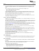
Table 17-13. Miscellaneous Instructions
Syntax Description Operation Z N C V
ld Rd,#simm Load immediate Rd = simm - - - -
ld Rd,Rs Load register Rd = rs - - - -
pfix #imm Prefix immediate pfix = imm - - - -
The load immediate instruction embeds a 10-bit signed immediate in the instruction word, allowing an
immediate in the range -512 to +511 to be loaded directly into a register.
The load register instruction copies a source register to a destination register. The nop instruction is
encoded as ld R7,R7.
The prefix instruction embeds an 8-bit, unsigned immediate in the instruction word that is loaded into a
hidden prefix register. Upon execution of the next instruction with an immediate or direct address operand,
the prefix register is effectively providing bit 15-8 of the source operand. Once used, the prefix register is
disabled and not used again until following the execution of a new prefix instruction.
1198
AUX – Sensor Controller with Digital and Analog Peripherals SWCU117A–February 2015–Revised March 2015
Submit Documentation Feedback
Copyright © 2015, Texas Instruments Incorporated