
User manual


Modules
www.ti.com
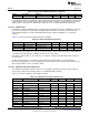
Table 17-4. Input and Output Instructions (continued)
Syntax Description Operation Z N C V
out Rd,(Rs) Output indirect reg[rs] = Rd - - - -
For instructions using direct peripheral register addressing, an 8-bit address is embedded in the instruction
supporting direct access to 256 I/O ports in the range 0 to 255. Using the prefix instruction, the direct I/O
address can be extended to 16. 16-bit addressing of I/O is also possible using indirect addressing.
17.4.1.5.3 I/O Bit Access
In addition to reading and writing I/O ports using the input and output instructions, individual bits in the I/O
ports can be directly set, cleared, and tested using single instructions. This allows very fast and code-
efficient implementation of common bit-manipulation functions, without requiring the use of internal
registers.
Table 17-5 shows the input and output instructions available.
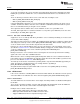
Table 17-5. Input and Output Instructions
Syntax Description Operation Z N C V
iobclr #imm,[#addr] I/O Bit Clear direct reg[addr] &= ~2^imm - - - -
iobset #imm,[#addr] I/O Bit Set direct reg[addr] |= 2^imm - - - -
iobtst #imm,[#addr] I/O Bit Test direct reg[addr] & 2^imm - - x -
The clear and set instructions first perform an input operation from the addressed register, then modify the
selected bit only and output the resulting new value to the same register.
Note that it is only possible to select bits 0 to 7 in a register using the 3-bit immediate value encoded in
the instructions.
Because the instructions use only direct register addressing, an 8-bit address is embedded in the
instruction supporting direct access to 256 registers in the range 0 to 255. Using the prefix instruction, the
direct register address can be extended to 16-bit.
17.4.1.5.4 Arithmetic and Logical Operations
The arithmetic and logical operations operate on a destination operand in an integer register, while the
source can be either another integer register, or an 8-bit immediate operand.
Table 17-6 shows the arithmetic and logical instructions.
Table 17-6. Arithmetic and Logical Instructions
Syntax Description Operation Z N C V
Dyadic instructions
add Rd,#simm
Add immediate Rd += simm x x x x
cmp Rd,#simm Compare immediate Rd – simm x x x x
and Rd,#imm AND immediate Rd &= imm x x 0 0
or Rd,#imm OR immediate Rd |= imm x x 0 0
xor Rd,#imm XOR immediate Rd ^= imm x x 0 0
tst Rd,#imm Test immediate Rd & imm x x 0 0
add Rd,Rs Add register Rd += Rs x x x x
sub Rd,Rs Subtract register Rd -= Rs x x x x
subr Rd,Rs Subtract reverse register Rd = Rs – Rd x x x x
cmp Rd,Rs Compare register Rd – Rs x x x x
and Rd,Rs AND register Rd &= Rs x x 0 0
or Rd,Rs OR register Rd |= Rs x x 0 0
1194
AUX – Sensor Controller with Digital and Analog Peripherals SWCU117A–February 2015–Revised March 2015
Submit Documentation Feedback
Copyright © 2015, Texas Instruments Incorporated